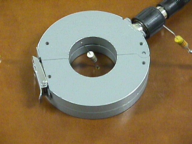
Figure 1. Measurement of Current Through an Inductor

Address: P. O. Box 1457, Los Gatos,
CA 95031
TEL:
800-323-3956/408-356-4186
FAX:
408-358-3799
Mobile: 408-858-4528
URL:
www.dsmith.org
Email: doug@dsmith.org
Figure 1. Measurement of Current Through an Inductor
Often a quick characterization of a component is needed and available equipment must be used because of time constraints. In the Technical Tidbit for February 2000 a method was described for measuring the parasitic resistance and inductance of a capacitor. In this Technical Tidbit, a method for measuring the high frequency performance (effected by parasitics) of an inductor is described.
Any device that is placed in a cradle or base to charge it's battery, such as a cordless or mobile phone, is subject to the effects of an ESD event as contact is made between the handheld device and the battery charger contacts in the base. One way of minimizing the effects of the ESD event is to put small inductors in series with the battery contacts of the handheld device. A problem arises in that the specification of inductor parameters is usually made at a low frequency between 1 kHz and 1 MHz whereas, in this case, the inductor is being subjected to frequencies much higher than that.
A quick way to measure the high frequency performance of an inductor is to use an ESD simulator and a current probe. Figure 1 above shows the measurement configuration. The inductors to be tested are soldered to a circuit board with a copper plane on one side. The current probe is placed on the opposite side so that it is insulated from the copper plane. An ESD simulator is discharged into each inductor while the current probe is placed around the inductor being tested. The copper plane is connected to ground to prevent it from being charged up by the ESD simulator. Examples of data taken this way is shown in Figures 2 through 5 below. The discharge voltage used was about 1 kV.
Figure 2 shows that the current through a 10 uH inductor has a spike
(high frequency component) and a broad rise (low frequency component).
While the broad rise is more impressive, the spike is more likely to cause
upset problems in equipment because of its much higher rate of change of
current (di/dt).
V = 0.5 Amp/div H = 10 ns/div
Figure 2. Current Through a 10 uH Inductor
In Figure 3, one can see that increasing the inductor from 10 to 22
uH reduces the low frequency component of current, but does little to reduce
the spike of current and therefore the interference potential.
V = 0.5 Amp/div H = 10 ns/div
Figure 3. Current Through a 22 uH Inductor
Figure 4 shows that a 100 uH inductor essentially kills the low frequency
component while actually increasing the amplitude of the narrow spike.
This inductor would increase the interference potential over the 10 or
22 uH inductors significantly.
V = 0.5 Amp/div H = 10 ns/div
Figure 4. Current Through a 100 uH Inductor
Figure 5 shows the resulting current when a 22 uH inductor is used in
series with a 100 uH inductor. The 100 uH inductor reduces the low frequency
component and the 22 uH inductor reduces the high frequency component.
This is analogous to using large and small bypass capacitors in parallel
on a printed wiring board to achieve a low impedance over a broad frequency
range. In this case, a small and large inductor are being used in series
to achieve a high impedance over a broad frequency range.
V = 0.5 Amp/div H = 10 ns/div
Figure 5. Current Through a 100 uH Inductor in Series with a 22 uH Inductor
The ESD simulator used with a current probe (Fischer F-33-1) and a fast digitizing scope clearly shows that the combination of the 22 uH and 100 uH inductors significantly reduces the likelihood of upset from an ESD event to a battery charging contact.