Inexpensive, but Useful Test Equipment
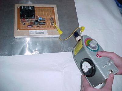
Figure 1. Using a "Dip Meter" to Measure Resonant Frequencies

Address: P. O. Box 1457, Los Gatos,
CA 95031
TEL:
800-323-3956/408-356-4186
FAX:
408-358-3799
Mobile: 408-858-4528
URL:
www.dsmith.org
Email: doug@dsmith.org
Figure 1. Using a "Dip Meter" to Measure Resonant Frequencies
Occasionally, equipment designed for one use has another use quite distinct from the intended one, but in another field. Such equipment is often very inexpensive and yields useful results. Such is the case for using a "Dip Meter" to find resonant frequencies of equipment. The instrument shown in Figure 1 above is actually called a "Grid-Dip Meter," a term used many years ago because the instrument used a vacuum tube oscillator. The one shown is about 40 years old. Newer units use solid state circuitry and are just called "Dip Meters." They are used by Amateur Radio operators to measure the resonant frequencies of tuned circuits and antennas.
The meter is used as follows; the frequency is varied (as shown on the multi-colored dial above) with the instrument coupled to the circuit. Energy is absorbed from the instrument at frequencies where the circuit is resonant causing the meter reading to "dip" and hence the name "Dip Meter." Figure 1 above shows this measurement on the test setup of the April, 2002 Technical Tidbit: "Printed Wiring Board Coupling to a Nearby Metal Plane." The meter operation is shown in Figures 2 and 3.
For Figures 2 and 3, the meter was tuned to a resonant frequency of the board over the metal plate. In Figure 2, the meter was not coupled into the circuit and exhibits a high reading. As the coil on the top of the meter is brought close to the wire connecting the board to the ground plane, the meter reading exhibits a significant "dip" (all the way to zero in this case). At other (non-resonant) frequencies of the circuit under test, the meter reading is not affected to a significant degree.
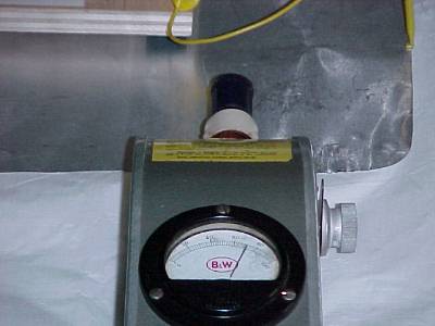
Figure 2. Dip Meter not Coupled to Circuit
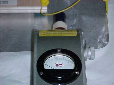
Figure 3. Dip Meter Coupled to Circuit
Such a method can be used to find the resonant frequencies of equipment designs including boards mounted over metal planes. One example of this is shown in Figure 4 for the setup used in the May, 2002 Technical Tidbit: "Printed Wiring Board Coupling to a Nearby Metal Plane, Part 2: ESD Immunity."
Knowing the resonant frequencies of a design can be useful in tracking down EMC related problems. Some dip meters have a strong signal and can be used to inject a continuous signal of variable frequency into circuits to help pinpoint radiated immunity problems.
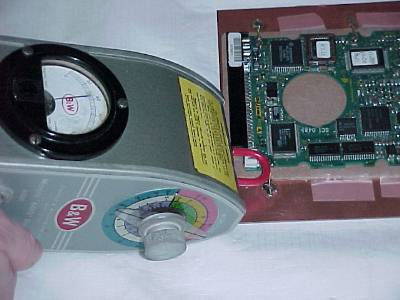
Figure 4. Method for Measuring Resonance of the May,
2002 Technical Tidbit Setup
Dip meters cost about US$100-$200. One source is MFJ Enterprises. Several links are included below, the first being a dip meter from MFJ Enterprises. Ham Radio Outlet is a chain of amateur radio stores where one can purchase such equipment.