High Frequency MeasurementsWeb Page
Douglas C. Smith

 Address:  P. O. Box 1457, Los Gatos,CA 95031
 TEL:     800-323-3956/408-356-4186
 FAX:     408-358-3799
 Mobile:   408-858-4528
 URL:     www.dsmith.org
 Email:    doug@dsmith.org


Technical Tidbit - January 2004
Determining the Effects of Probing on Signals - Tuned Probe Simulators

 tuned probe tester - passive 10x probe
Figure 1. Passive 10X Hi-Z Probe with Tuned Probe Simulator

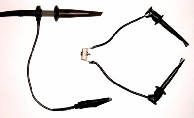
Abstract:  Probing can have significant effects onthe signals being measured. One of these effects, resonance between probe input capacitanceand lead inductance, can be simulated with a trimmer capacitor and its connectingleads. Such a "tuned probe simulator" can both provide insight on how probingaffects signals and help troubleshoot circuit problems as well. Tuned probesimulators for passive and active probes are discussed.

Discussion: Probes whose input impedance is primarily capacitive,such as the old standby 10X Hi-Z probe and most active probes, can significantly affectcircuits to be measured. This happens when the probe input capacitance resonates with theinductance of the probe connections to form a series tuned circuit. Such a circuit can have verylow input impedance at the resonant frequency. The resonance can affectthe measured waveform, induce error in the measured result, and both causeand "fix" circuit problems.

Figure 1 shows a standard "Hi-Z" 10X passive probe on the left and a tunedprobe simulator on the right that can mimic the probe's effect on a circuitto be measured. To construct a tuned probe simulator, start with a test leadthat is about the same length as the probe signal path dimensions. The totallength of the tuned probe simulator should be approximately equal to thelength of the probe tip and ground lead length. Cut the test clip in themiddle and insert a variable trimmer capacitor that has a range from about1/2 to about 2 times the input capacitance of the probe. Figure 2 shows sucha construction for an active probe. The important factors are that the lengthof the simulator be about the dimensions of the probe's connections and the trimmer capacitorhave a range of at least a factor of two above and below the probe input capacitance.

  Active Probe with Tuned Probe Tester
Figure 2. Active Probe with Tuned Probe Simulator

If the probe has an input damping resistor, as many recently designedactive probes do, be sure to add the same amount of resistance in serieswith the trimmer capacitor. Typical values range from 100 to 200 Ohms. Likewise,for the probe in Figure 2, it would be a good idea to add a small ferritecore to the simulator that has characteristics similar to the one used onthe probe. A 100 ohm resistor can be used as an approximate substitute ifa suitable ferrite core is not available.A tuned probe simulator for an active probe, such as shown in Figure 2, mayneed to soldered to the circuit so the trimmer can be adjusted. Be carefulto use a non-conductive tuning tool and not to touch the trimmer or its connectionswith fingers during the adjusting process.

Sometimes, connection of a probe to a circuit may cause the circuitto start working! One way this happens can be described with reference toFigure 3. The figure shows the input impedance of a typical active probe configuration thatdoes not have a series damping resistor in series with its input. Notice the strong resonancejust below 1 GHz where the input impedance dips as low as 17 Ohms, a typicalvalue. The probe essentially has placed a notch filter on the circuit tobe measured. If the source of the circuit malfunction has significant energyin the neighborhood of the resonance, the circuit may start to work whenthe probe is connected.


active probe input z graph
Figure 3. Active Probe Input Impedance Example
Input Z (2000-17 Ohms) vs. Frequency (100MHz-5GHz)

One way to determine if this is happening is to replace the probe with asuitably constructed tuned probe simulator. The trimmer capacitor is tunedthrough its range and if the circuit starts to work, then probe resonanceis likely affecting the circuit. Likewise, a tuned probe simulator can be used to see if aprobe will load a circuit, even if the probe is not available. If one is consideringpurchasing an active probe, a tuned probe simulator can allow youto estimate the effect on your circuits.

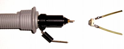
Summary and Conclusion: Probing a signal can affect itin several ways. One way this can happen is the resonance of probe input capacitance withthe connection inductance resulting in a very low probe input impedance atthe resonant frequency. Tuned probe simulators can be useful both as a troubleshootingtool to investigate this effect as well as to predict possible loading froma probe being considered for purchase.

History:  Originally, Henry Ott, describeda "tuned probe tester" years ago in his EMC seminars. This article takesthe concept further in applying the principle to active probes and its usein predicting circuit response to a probe before it it purchased.

Other articles on this website covering probing effects include:

Equipment used in this article includes:

Top of page
Home


Questions or suggestions? Contact me at doug@dsmith.org
Copyright © 2004 Douglas C. Smith