
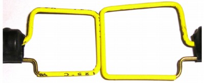
Figure 1. Coupling a Signal Between Two Loops
Abstract: A square wire loop excited by a signal generator can be used to
inject pulses or RF signals precisely into a circuit without disturbing
circuit conditions. Used in this way, such a loop can be a
significant aid in design troubleshooting. Suggestions for such uses
are given.
Discussion: Many other articles on this website discuss using loops to measure signals and noise in a circuit. In this article, just the opposite is discussed, injecting signals and noise into circuits.
Figure 1 shows two similar loops constructed from stiff wire and held adjacent to each other. If one loop is driven from a signal generator, a significant signal can be coupled into the other loop. Either a pulse or continuous wave RF signal generator may be used. The loop to loop transmission, such as in Figure 1, gives an estimate of what is possible to inject into any nearby circuit. Injection into printed wiring boards using ground and power planes will be smaller than the loop to loop transmission because of the planes in the board. In that case, the injected noise can be measured with an oscilloscope connected to the circuit.
If an energized loop is held close to a circuit, the pulses or RF signal can be injected precisely into parts of the circuit for troubleshooting purposes. Injecting noise into a circuit this way does not affect the DC operating conditions of the circuit and has minimal effect on AC conditions except for the noise induction.
For the case shown in Figure 1, the loops are made of 16 gauge brass wire purchased from a hardware store and covered with heat shrink tubing. One end of each loop is soldered to the side of a BNC barrel adapter and the other end of the wire is inserted into the center of the BNC adapter. A convenient size for such loops is about two cm or one inch. The loop size should be such as to allow access to the circuit to be tested.
Figure 2 shows the output from one loop of Figure 1, about 2.5 cm, when the other loop is driven from an IEC 61000-4-4 electrical fast transient (EFT) generator. The 50 Ohm IEC generator is set to 250 Volts and the receiving loop is connected to the 50 Ohm input of an oscilloscope. 50 Ohm coaxial cable was used to connect both loops. It is important to make sure the brass wire is securely soldered to the shield of the coaxial cable from the generator, the BNC barrel adapter in this case. If the ground side of the loop comes loose, the full open circuit output of the EFT generator, as much as 4000 Volts, will be present on the loop and an RF burn to the skin or circuit damage is possible.
The EFT generator has a 50 Ohm output, so the 250 Volt setting gives a five Ampere short circuit current through the loop neglecting the drop across the loop itself to a first order approximation. For reasonable assumptions on wire size and a 2.5 cm loop, the inductance of the loop is about 80 nH and the voltage across the inductance the loop is approximately given by:
Figure 2. 250 Volt EFT Coupled Signal Between 2.5 cm Square Loops
Continuous RF signals can also be injected if an RF signal generator is used to excite a loop. In many instances, an output of +10 to +13 dBm is adequate to elicit problems to show themselves in a circuit.
Summary: Using nothing more than a wire loop, pulses and RF signals can be precisely injected into circuits for troubleshooting purposes. Significant noise can be injected with amplitudes of several Volts or more possible.
Discussion: Many other articles on this website discuss using loops to measure signals and noise in a circuit. In this article, just the opposite is discussed, injecting signals and noise into circuits.
Figure 1 shows two similar loops constructed from stiff wire and held adjacent to each other. If one loop is driven from a signal generator, a significant signal can be coupled into the other loop. Either a pulse or continuous wave RF signal generator may be used. The loop to loop transmission, such as in Figure 1, gives an estimate of what is possible to inject into any nearby circuit. Injection into printed wiring boards using ground and power planes will be smaller than the loop to loop transmission because of the planes in the board. In that case, the injected noise can be measured with an oscilloscope connected to the circuit.
If an energized loop is held close to a circuit, the pulses or RF signal can be injected precisely into parts of the circuit for troubleshooting purposes. Injecting noise into a circuit this way does not affect the DC operating conditions of the circuit and has minimal effect on AC conditions except for the noise induction.
For the case shown in Figure 1, the loops are made of 16 gauge brass wire purchased from a hardware store and covered with heat shrink tubing. One end of each loop is soldered to the side of a BNC barrel adapter and the other end of the wire is inserted into the center of the BNC adapter. A convenient size for such loops is about two cm or one inch. The loop size should be such as to allow access to the circuit to be tested.
Figure 2 shows the output from one loop of Figure 1, about 2.5 cm, when the other loop is driven from an IEC 61000-4-4 electrical fast transient (EFT) generator. The 50 Ohm IEC generator is set to 250 Volts and the receiving loop is connected to the 50 Ohm input of an oscilloscope. 50 Ohm coaxial cable was used to connect both loops. It is important to make sure the brass wire is securely soldered to the shield of the coaxial cable from the generator, the BNC barrel adapter in this case. If the ground side of the loop comes loose, the full open circuit output of the EFT generator, as much as 4000 Volts, will be present on the loop and an RF burn to the skin or circuit damage is possible.
The EFT generator has a 50 Ohm output, so the 250 Volt setting gives a five Ampere short circuit current through the loop neglecting the drop across the loop itself to a first order approximation. For reasonable assumptions on wire size and a 2.5 cm loop, the inductance of the loop is about 80 nH and the voltage across the inductance the loop is approximately given by:
E = Ldi/dt ~ 80nH(5A/5ns) ~ 80V
(this is small compared to the drop across the 50 Ohm source impedance of the generator)
The voltage drop across one side of the loop would be about one fourth of
80 Volts or about 20 Volts. Since the output of the receiving loop reached
almost 4 volts, about 1/5 of the 20 Volt drop in the adjacent side of the
energized loop was coupled into the receiving loop, a typical number.(this is small compared to the drop across the 50 Ohm source impedance of the generator)
Figure 2. 250 Volt EFT Coupled Signal Between 2.5 cm Square Loops
Imagine now, holding an energized loop next to a wire whose insulation thickness was similar to that of
the receiving loop (thicker insulation would reduce coupling). A
similar voltage to that shown in Figure 2 would be injected in series
with the wire since the coupling is mostly inductive. The exact value of coupled noise would be affected by nearby ground/power planes or metal and can be determined
with an oscilloscope. Using this technique, one can inject pulses of known amplitude into
precise locations in a circuit to see how the circuit reacts for
troubleshooting purposes.
Continuous RF signals can also be injected if an RF signal generator is used to excite a loop. In many instances, an output of +10 to +13 dBm is adequate to elicit problems to show themselves in a circuit.
Summary: Using nothing more than a wire loop, pulses and RF signals can be precisely injected into circuits for troubleshooting purposes. Significant noise can be injected with amplitudes of several Volts or more possible.
Other articles on this website related to this topic are:
-
Signal and Noise Measurement Techniques Using
Magnetic Field Probes (~600K)
- (1999 IEEE EMC Symposium paper)
- August 1999: The Paperclip Magnetic Probe
- April 2000, Paper Clips and the Speed of Light
- November 2000, Measuring the Effects of High Frequency Noise Currents in Equipment
- December 2000, An Easy to Build Shielded Magnetic Loop Probe
- February 2001, Switching Power Supplies - Effects on Circuits, Magnetic Fields
- March 2001, Switching Power Supplies - Common Mode Conducted Noise on Outputs
- June 2002, Using Mutual Inductance to Measure Voltage Drop in Circuits
- January 2003, Crossing Ground Plane Breaks - Part 2, Tracing Current Paths
- April 2003, Measurement and Interpretation of High Frequency Chip Noise
- April 2004, Paper Clips, They're Not Just For Emissions Anymore!
- April 2005, Inductive and Capacitive Coupling - Induced Current Characteristics
If you like the information in this article and others on this website, much more information is available in my courses. Click here to see a listing of upcoming courses on design, measurement, and troubleshooting of chips, circuits, and systems.
Available now for private on-site delivery and as a public seminar: my new one day seminar titled: Failure Analysis and Prevention in Electronic Circuits (Design Troubleshooting for the Lab and Field).
Equipment used in this article includes:
- Agilent Infinium 54845a scope
- IEC 61000-4-4 EFT generator
- Home made loop from 16 gauge brass wire and a BNC connector
Home