
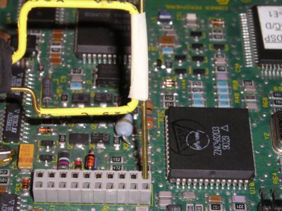
Figure 1. Checking Circuit Ground at a Connector for Noise
Abstract: An area of a circuit board or system
that has significant noise present on ground can often drive common mode currents
on cables or other structures causing excessive emissions. A simple
technique is described to identify areas of a circuit board or system
that are at risk for emissions problems.
Figure 1 shows a square magnetic loop attached to a wire checking a gound pin of a connector for the ability to drive common mode current on a cable. Figure 2 shows the whole loop and wire assembly. The loop is attached to the wire by paper masking tape and the wire length is about one foot or about 30 cm, a length useful in the 150 to 200 MHz range. A spectrum analyzer with a 50 Ohm input impedance is then usually used to measure the loop output voltage into 50 Ohms.
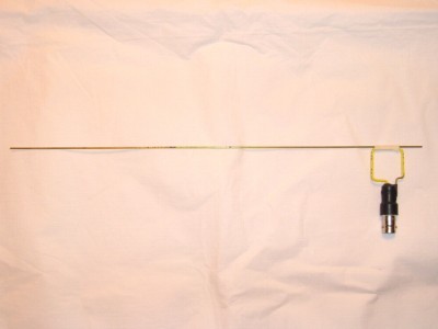
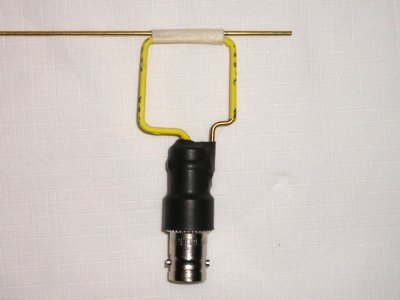
Figure 3 shows a close-up of the loop. I can remember Henry Ott using a current probe at the base of a one meter wire many years ago to check for "hot grounds." This is essentially the same technique, except adapted for today's higher frequencies and smaller products. The wire used should be about one quarter wavelength in the center of a frequency band of interest. A typical frequency range might be 150 to 200 MHz, a ratio of about 4:3. For this frequency range, a 30 cm (one foot) wire works well.
If a frequency is scanned that is too far from the quarter wave frequency of the wire, one might not see much current even though noise is present, it is just that the wire is not providing a low enough impedance to accept current. For a wire that is one half wavelength, it will present a very high impedance and little current can flow at that frequency.
A shielded magnetic loop works best, but a simple wire loop like that in Figure 3 is often adequate. The loop is really being used as a current probe in this technique. The transfer impedance of the loop as a current probe (ratio of voltage out to current in the attached wire) in the "flat response" frequency range of the loop (see below) is given by:
where:
This equation is derived in Chapter 8 of my book, High Frequency Measurements and Noise in Electronic Circuits.
It is the result of placing an L-R voltage divider (loop L and 50 Ohm
load) on the open circuit output of the loop, Mdi/dt, and grinding
equations for a page or two making substitutions along the way.
For a one inch (~2.5 cm) per side square loop, the flat region of frequency response ranges from about 100 MHz to just above 1 GHz. In this frequency range, the transfer impedance is often near 5 Ohms for thin insulation and typical wire sizes (L~80 nH and M~8 nH). This means the output of the loop is comparable to an F-33-1 current probe and the calculations in the March, 2006 Technical Tidbit, "Predicting Cable Emissions from Common Mode Current" can be applied to the loop. Thus a loop output above 100 MHz of ~38 dBuV indicates enough common mode current on the wire that ground in that area is "hot" and may cause nearby attached cables to radiate excessive emissions. Above a few hundred MHz, emissions limits are several dB higher and levels above ~38 dBuV from the loop may be acceptable.
In a typical current probe, a magnetic core is used. The self inductance of the probe's winding, L, and mutual inductance to the wire, M, can be calculated and are relatively constant. Thus the current probe can be calibrated. When using a loop as a current probe, M is a function of insulation thickness and is variable. The equations that describe both probes are identical, M and L are just different for the two cases, generally lower for the loop because there is no magnetic core. See my Technical Tidbit for September 1999 for more information or chapter eight of my book for even more details on current probes (probably too many details!).
The advantage of using a loop as a current probe is its small size and ease of attachment to a wire. The loop could even be considered a "handle" to hold the wire. This allows access to crowded circuit boards at the expense of calibration accuracy. Sometimes, only a relative measurement is needed, so calibration is not an issue. A wire on the order of one quarter wavelength is also small in the hundreds of MHz frequency range so the whole assembly is small enough to get in tight spaces on a circuit board in an enclosure. Once the frequencies get above one GHz, a smaller loop is needed. The circumference of the loop should be smaller than one half wavelength to avoid loop resonance.
Summary: The combination of a small square loop and a piece of wire can be a powerful tool to find "hot" areas of ground on a circuit board or in a system.
Discussion: One way of finding "hot"
areas of a circuit ground is to attach a wire to act like an antenna and see if it
is driven with substantial common mode current. Common mode current on
a conductor can be directly related to radiated emissions. Click here
to read the Technical
Tidbit for March 2006, "Predicting Cable Emissions from Common Mode
Current" on this site for a discussion on common mode currents and
emissions. If a wire attached to a board is driven with enough current
to cause excess emissions (15 uAmps or more is generally enough), then
there is a risk that a nearby cable or other structure attached near
the same point on the board could radiate excessive emissions as well.
Figure 1 shows a square magnetic loop attached to a wire checking a gound pin of a connector for the ability to drive common mode current on a cable. Figure 2 shows the whole loop and wire assembly. The loop is attached to the wire by paper masking tape and the wire length is about one foot or about 30 cm, a length useful in the 150 to 200 MHz range. A spectrum analyzer with a 50 Ohm input impedance is then usually used to measure the loop output voltage into 50 Ohms.
Figure 2. One Inch Magnetic Loop Attached to "Antenna" Wire
Figure 3 shows a close-up of the loop. I can remember Henry Ott using a current probe at the base of a one meter wire many years ago to check for "hot grounds." This is essentially the same technique, except adapted for today's higher frequencies and smaller products. The wire used should be about one quarter wavelength in the center of a frequency band of interest. A typical frequency range might be 150 to 200 MHz, a ratio of about 4:3. For this frequency range, a 30 cm (one foot) wire works well.
If a frequency is scanned that is too far from the quarter wave frequency of the wire, one might not see much current even though noise is present, it is just that the wire is not providing a low enough impedance to accept current. For a wire that is one half wavelength, it will present a very high impedance and little current can flow at that frequency.
Figure 3. Close-up of Magnetic Loop Attached to Wire
A shielded magnetic loop works best, but a simple wire loop like that in Figure 3 is often adequate. The loop is really being used as a current probe in this technique. The transfer impedance of the loop as a current probe (ratio of voltage out to current in the attached wire) in the "flat response" frequency range of the loop (see below) is given by:
ZT = (M/L)RL
where:
- ZT is the loop probe transfer impedance.
- L is the self inductance of the loop.
- M is the mutual inductance between the loop and attached wire.
- RL is termination resistance of the loop, usually th 50 Ohm input of a spectrum analyzer in this case.
For a one inch (~2.5 cm) per side square loop, the flat region of frequency response ranges from about 100 MHz to just above 1 GHz. In this frequency range, the transfer impedance is often near 5 Ohms for thin insulation and typical wire sizes (L~80 nH and M~8 nH). This means the output of the loop is comparable to an F-33-1 current probe and the calculations in the March, 2006 Technical Tidbit, "Predicting Cable Emissions from Common Mode Current" can be applied to the loop. Thus a loop output above 100 MHz of ~38 dBuV indicates enough common mode current on the wire that ground in that area is "hot" and may cause nearby attached cables to radiate excessive emissions. Above a few hundred MHz, emissions limits are several dB higher and levels above ~38 dBuV from the loop may be acceptable.
In a typical current probe, a magnetic core is used. The self inductance of the probe's winding, L, and mutual inductance to the wire, M, can be calculated and are relatively constant. Thus the current probe can be calibrated. When using a loop as a current probe, M is a function of insulation thickness and is variable. The equations that describe both probes are identical, M and L are just different for the two cases, generally lower for the loop because there is no magnetic core. See my Technical Tidbit for September 1999 for more information or chapter eight of my book for even more details on current probes (probably too many details!).
The advantage of using a loop as a current probe is its small size and ease of attachment to a wire. The loop could even be considered a "handle" to hold the wire. This allows access to crowded circuit boards at the expense of calibration accuracy. Sometimes, only a relative measurement is needed, so calibration is not an issue. A wire on the order of one quarter wavelength is also small in the hundreds of MHz frequency range so the whole assembly is small enough to get in tight spaces on a circuit board in an enclosure. Once the frequencies get above one GHz, a smaller loop is needed. The circumference of the loop should be smaller than one half wavelength to avoid loop resonance.
Summary: The combination of a small square loop and a piece of wire can be a powerful tool to find "hot" areas of ground on a circuit board or in a system.
Other articles on this website related to this topic are:
- March 2006, Predicting Cable Emissions from Common Mode Current
- September 1999, Using a Current Probe to Directly Measure Voltage Drop in a Circuit
- Signal and Noise Measurement Techniques Using Magnetic Field Probes (~600K)
- (1999 IEEE EMC Symposium paper)
- Current Probes, More Useful Than You Think (~600K)
- (1998 IEEE EMC Symposium paper)
Click here for a description of my latest seminar to be available in the Fall titled:
EMC
Lab Techniques for Designers
(How to find EMC problems and have some confidence your system will pass EMC testing while it is still in your lab).
(How to find EMC problems and have some confidence your system will pass EMC testing while it is still in your lab).
 |
Check out my podcast containing mp3 format short tutorials, tech news and more! Just click on the microphone to see the listing
of free
audio programs. Content is added every week on technical topics so check back frequently. |
Home