
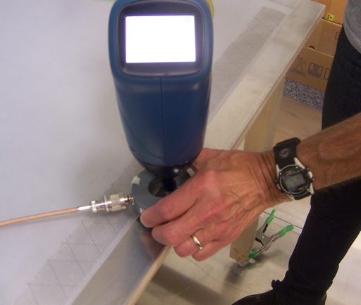
Figure 1. Test Setup for Measuring ESD Current From an ESD Simulator
Abstract: IEC 61000-4-2
compliant ESD Simulators (150 pF/330 Ohm network) are required to meet
a specified waveform. Results are presented here comparing the current
waveforms delivered into a metal tabletop (Horizontal Coupling Plane of
IEC 61000-4-2) by three different simulators. The results were not as
uniform as expected. The data presented has implications for the
reproducibility of ESD testing.
Discussion: This Technical Tidbit is an extension of the November 2010 Technical Tidbit and uses the same test method to compare three different 150 pF/ 330 Ohm, IEC 61000-4-2 compliant ESD simulators.
Figure 1 shows the overall test setup for measuring the current waveform. The simulator ground lead was connected to the metal plane on the top of the table, the Horizontal Coupling Plane of the IEC 61000-4-2 test (instead of performing the test on the floor Reference Ground Plane). The test was done near the edge of the table so the waveforms will not be exactly the same as the calibration waveform in IEC 61000-4-2, but a valid comparison of the simulators can be made. Current was measured with a Fischer F-65 one GHz current probe and Agilent 54845a oscilloscope.
Figure 2 shows a close-up of the measurement of current injected onto the table top metal plane. The discharge tip of the simulator easily fits through the F-65 current probe. I am holding the current probe slightly off the ground plane so as to minimize common mode ESD current from traveling down the coax shield to the scope. There were several ferrite cores on the coax at the scope to suppress common mode ESD currents there as well. The coaxial cable used was RG-142B/U. Its shielding effectiveness is extremely good and RG142B/U coaxial cable is well suited for making ESD measurements with the F-65 one GHz current probe.
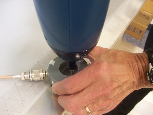
Figure 3 shows the discharge current for a 1 kV contact discharge using the 150 pF/330 Ohm network of a rented Teseq NSG438 simulator. Figures 4 and 5 show the discharge currents for KeyTek MiniZap and Haefely Onyx simulators respectively measured with the same test setup. The ONYX current was plotted at a scale factor of 2X higher sensitivity and so looks larger, but I am interested in mostly the shape of the current waveform for this comparison. The MiniZap was used with the high speed tip (as opposed to the IEC tip) which gives a risetime of about 300 ps and a slightly larger initial spike at the start of the current waveform.
Figure 3. Current Waveform Generated by the Rented Teseq NSG438 ESD Simulator
Figure 5. Current Waveform Generated by the Haefely ONYX ESD Simulator
Notice that the initial current spike in Figure 3 is much smaller compared to the rest of the waveform than it was for the other two simulators and that there is a double hump in the low frequency part of the waveform of Figure 3 that is not evident in the other two current waveforms. These differences could easily influence the outcome to an ESD test.
The hash on the waveform in Figure 3, and to a lesser extent in Figures 4 and 5, is as result of radiated EMI affecting the scope that was only about one and a half meters from the discharge point.
The "hash" starting about 7 ns before before the current waveform in all three cases is due to EMI from the ESD simulator and current discharge radiating directly into the scope as well. The hash starts 7 ns earlier because the air path to the scope has 7 ns less delay than the current waveform traveling down the coaxial cable to the scope. The hash can be reduced by averaging several waveforms. An example of this approach will be covered in next month's Technical Tidbit for January 2011.
Rented ESD simulators experience high levels of usage and likely experience a rough life. This could explain the waveform in Figure 1. I would recommend when using rented ESD simulators that such simulators be checked out by the user at the start of testing. The Fischer F-65 current probe is a great tool for doing this. Just discharge though the probe into a large piece of metal to which the simulator ground lead is attached and see if the current waveform looks something like an IEC pulse. This is not an official calibration, rather a quick check to look for gross problems in the simulator.
Summary:Comparison
of the current discharge from three ESD simulators showed significant
differences in current waveforms. To insure accurate testing, I
recommend a quick check of the current waveform of the ESD simulator at
the start of the workday. Shooting through a current probe into a large
sheet of metal is an adequate test than can be done quickly.
Figure 1 shows the overall test setup for measuring the current waveform. The simulator ground lead was connected to the metal plane on the top of the table, the Horizontal Coupling Plane of the IEC 61000-4-2 test (instead of performing the test on the floor Reference Ground Plane). The test was done near the edge of the table so the waveforms will not be exactly the same as the calibration waveform in IEC 61000-4-2, but a valid comparison of the simulators can be made. Current was measured with a Fischer F-65 one GHz current probe and Agilent 54845a oscilloscope.
Figure 2 shows a close-up of the measurement of current injected onto the table top metal plane. The discharge tip of the simulator easily fits through the F-65 current probe. I am holding the current probe slightly off the ground plane so as to minimize common mode ESD current from traveling down the coax shield to the scope. There were several ferrite cores on the coax at the scope to suppress common mode ESD currents there as well. The coaxial cable used was RG-142B/U. Its shielding effectiveness is extremely good and RG142B/U coaxial cable is well suited for making ESD measurements with the F-65 one GHz current probe.
Figure 2. Close-up of Current Measurement
Figure 3 shows the discharge current for a 1 kV contact discharge using the 150 pF/330 Ohm network of a rented Teseq NSG438 simulator. Figures 4 and 5 show the discharge currents for KeyTek MiniZap and Haefely Onyx simulators respectively measured with the same test setup. The ONYX current was plotted at a scale factor of 2X higher sensitivity and so looks larger, but I am interested in mostly the shape of the current waveform for this comparison. The MiniZap was used with the high speed tip (as opposed to the IEC tip) which gives a risetime of about 300 ps and a slightly larger initial spike at the start of the current waveform.
Figure 3. Current Waveform Generated by the Rented Teseq NSG438 ESD Simulator
Figure 4. Current Waveform Generated by the MiniZap ESD Simulator
Figure 5. Current Waveform Generated by the Haefely ONYX ESD Simulator
Notice that the initial current spike in Figure 3 is much smaller compared to the rest of the waveform than it was for the other two simulators and that there is a double hump in the low frequency part of the waveform of Figure 3 that is not evident in the other two current waveforms. These differences could easily influence the outcome to an ESD test.
The hash on the waveform in Figure 3, and to a lesser extent in Figures 4 and 5, is as result of radiated EMI affecting the scope that was only about one and a half meters from the discharge point.
The "hash" starting about 7 ns before before the current waveform in all three cases is due to EMI from the ESD simulator and current discharge radiating directly into the scope as well. The hash starts 7 ns earlier because the air path to the scope has 7 ns less delay than the current waveform traveling down the coaxial cable to the scope. The hash can be reduced by averaging several waveforms. An example of this approach will be covered in next month's Technical Tidbit for January 2011.
Rented ESD simulators experience high levels of usage and likely experience a rough life. This could explain the waveform in Figure 1. I would recommend when using rented ESD simulators that such simulators be checked out by the user at the start of testing. The Fischer F-65 current probe is a great tool for doing this. Just discharge though the probe into a large piece of metal to which the simulator ground lead is attached and see if the current waveform looks something like an IEC pulse. This is not an official calibration, rather a quick check to look for gross problems in the simulator.
I would like to thank RMV Technology Group at NASA Ames Research Center for use of their facilities to generate the data for this Technical Tidbit.
Additional articles on this website related to this topic are:
- Novermber 2010, Comparison of Current Waveforms from 150 Ohm and 330 Ohm Networks in an IEC 61000-4-2 Simulator
- September 2004, Mobile Phone Response to EMI from Small Metal ESD
(for an example of ESD radiated noise into a scope measurement)
- Teseq NSG 438 ESD Simulator (700K pdf file)
- Haefely ONYX ESD Simulator
- KeyTek Mini-Zap ESD Simulator
- Fischer Custom Communications F-65 Currrent Probe
- Agilent Infinium 54845a scope
I would like to thank RMV Technology Group for the use of their facilities to perform the tests for this article.
Need help with a design or additional training on technical subjects? Click on the image below to go to CircuitAdvisor.com, a new engineering resource for training, news, and fun.
Need help with a design or additional training on technical subjects? Click on the image below to go to CircuitAdvisor.com, a new engineering resource for training, news, and fun.

If you like the information in this article and others on this website,
much more information is available in my courses. Click here
to see a listing of upcoming courses on design, measurement, and
troubleshooting of chips, circuits, and systems. Click here to see upcoming seminars in Newport Beach, CA.
Click here for a description of my latest seminar titled (now also available online as a WebEx seminar):
EMC
Lab Techniques for Designers
(How to find EMC problems and have some confidence your system will pass EMC testing while it is still in your lab).
(How to find EMC problems and have some confidence your system will pass EMC testing while it is still in your lab).
Home