Abstract: Radiated emissions
measurements of table top equipment are usually made with the equipment
placed on a non-conductive table. But such equipment is often used on
conductive surfaces, like a metal desk, and can couple to the
conductive surface to enhance emissions, essentially turning the
conductive surface into part of an antenna structure. When this
happens, standard testing of emissions can understate actual emissions.
A Class D (actually labeled Class Z) stereo amplifier is used to
illustrate this effect by measuring common mode current on its cables.
Class D (and newer
class "Z") digital audio amplifiers are potentially a source of noise
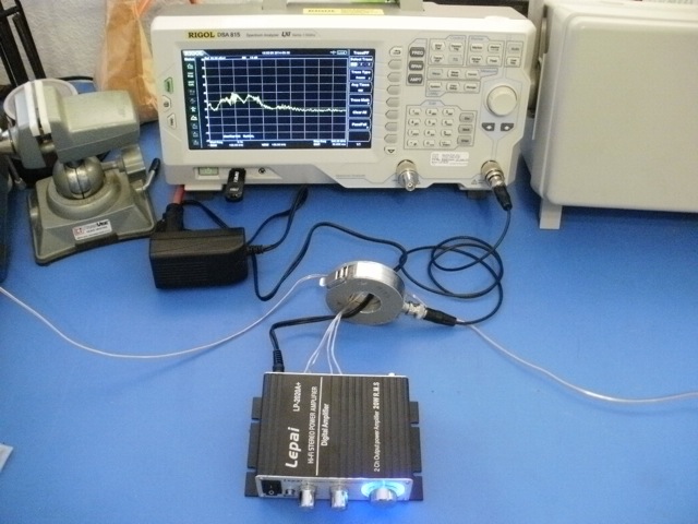
strong enough to exceed international radiated emissions limits. Figure
1 shows the test setup for a Lepai LP-2020A+ digital class Z
stereo amplifier. Two 8 Ohm power resistors serve as speaker loads and
are connected at the ends of the small wires exiting to the right and
left. A Fischer F-33-1 current probe is placed over the power and
speaker leads from the amplifier. The amplifier is sitting on a blue
ESD mat covering the table.
For this test, no input source of
audio was used. Behavior of the amplifier driven with an audio signal will be the subject of another Technical Tidbit.
Since the amplifier easily fits into the palm of a hand, it should
not be able to drive much common mode current out all the cables in
phase as the
amplifier case would have to be the other half of the antenna and it is
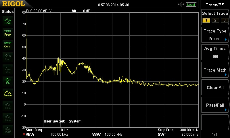
too small to act like an efficient antenna below 100 MHz. Yet in Figure
2, the common mode current on the cables would likely cause emissions
that
would equal or exceed Class B from 30 MHz up to a little over 100 MHz.
The common mode current is plotted from 0 to 300 MHz. The level of
common mode current that could cause emissions from the cables to reach
the CISPR Class B
limit from 30 MHz to just above 200 MHz is at 30 dBuV (left scale on
the plot).
The plot is at 30 dBuV or more for much of the range from about 30 MHz
to about 110 MHz, a likely emissions failure.
The amplifier actually is emitting noise over a wide band but the
common mode current flows for those frequencies for which the driving
impedance of the cables is low, that is, one or more of the cables is near 1/4
wave resonance. In this case the speaker wires are 2 meters long and
that explains the amplitude in the 30-40 MHz range.
Figure 2. Common Mode Current from Setup in Figure 1
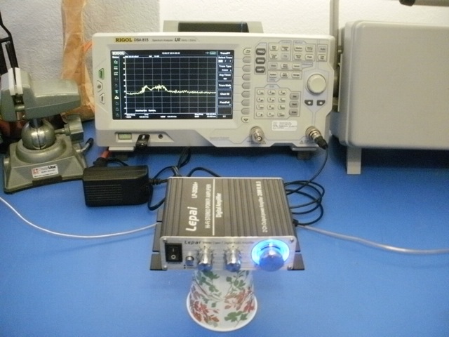
In Figure 3, the amplifier is raised up 9.5 cm on a paper cup over the
ESD mat the amplifier had been setting on. The a top view of the
setup is shown in Figure 4.
Figure 3. Amplifier Raised 9.5 cm Above ESD Mat
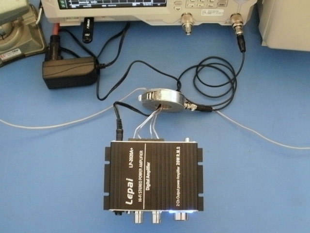
Figure 4. Top View of Amplifier Raised 9.5 cm Above ESD Mat
The resultant common mode current on the cables is shown in Figure
5 and is at or below 30 dBuV across the range, quite a decrease!
Apparently the amplifier chassis is coupling to the ESD mat core which
is apparently conductive enough (ESD mats often have a conductive core
and a high resistance outer surface) to act as the other half of the
antenna for the cables, sometimes called a counterpoise. When the
amplifier is raised off the mat, this coupling is decreased, and the
amplifier cannot drive as much current on the cables because it must
rely more on its small enclosure as the counterpoise.
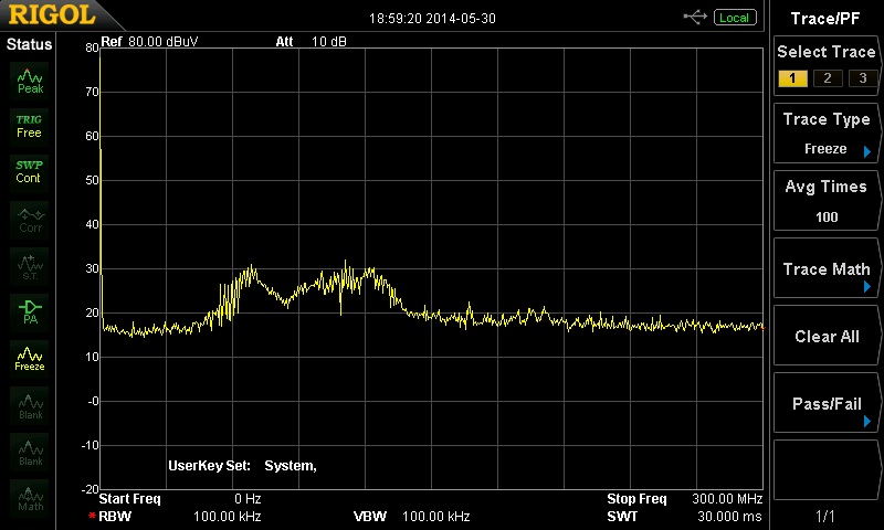 Figure 5.
 Common Mode Current on Leads of Amplifier Raised 9.5 cm Above ESD Mat
Figures 6 and 7 show the amplifier
back down on the ESD mat, but with a ferrite installed and the
resulting common mode current on the wires respectively.
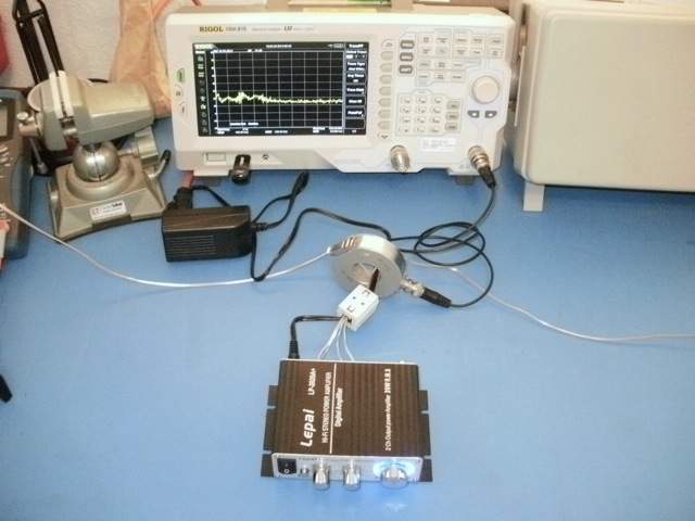 Figure 6.
 Ferrite Added to Leads From Amplifier
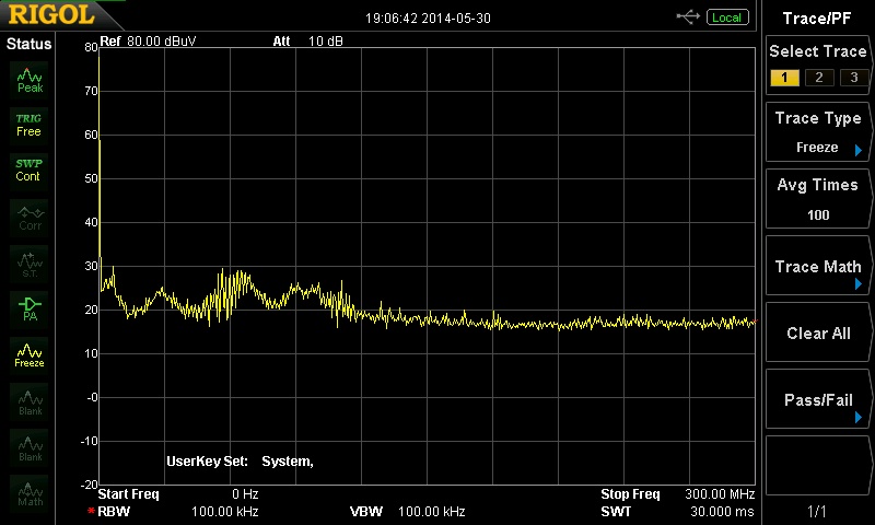 Figure 7.
 Common Mode Current on Leads of Amplifier on ESD Mat With Ferrite on Leads
The common mode current is below 30 dBuV now across the range, and
the amplifier with its ferrite core and cables is likely to pass an
emissions test, at least from cable emissions due to driving the cables in phase relative to the amplifier chassis.
The important point to be made is that emissions testing for table top
gear is normally performed on a non-conductive table. Based on the
performance with the amplifier raised on the cup, I suspect the
emissions test may be passed. But, what if the amplifier is used on a
conductive (metal) desk or placed on the metal enclosure of a cable TV
set top box? The proximity of the metal will allow more current to flow
on the amplifier leads, causing increased emissions. In this and
similar cases, official radiated emissions testing would understate
the emissions.
Summary: Class D
amplifiers can make good noise sources for experiments. In this case,
standard radiated emissions testing for compliance may understate
emissions from some devices that couple to conductive table tops.
Technical Tidbit on this site related to this article:
Equipment used in this Technical Tidbit: