Test & Measurement World
| ESDis a powerful source of interference that can cause electronic systemsto reset, lose data, or fail to operate. While standards require thatyou prove your product can withstand ESD, you should also test yourproduct under conditions that more closely simulate the environmentin which your customer will use it. Should your product continue to operate flawlessly at both your site andat your customer’s site after ESD tests, then you have a robust product.If your system operates at subpar levels during or after an ESD test,however, then you need to investigate how the energy from an ESD evententers your system. You can perform your investigations by measuringthe current that ESD exerts on your system. Atypical ESD event can send several amperes of current driven by thousandsof volts into your product. Those voltages and currents can causea product to function improperly or they can fatally damage circuits.(" How ESD Affects Circuits ,"below, explains these voltages and currents in more detail.) The damagethat ESD inflicts on circuits can also induce problems in your testequipment. And test equipment can place an additional load on yourEUT, which can alter your EUT’s ESD susceptibility. Tomeasure the effects of ESD in electronic equipment, you needseveral tools, including at least one ESD simulator, an oscilloscope,and current probes. Plus, you need BNC cables to connectthe probes to your scope. Be sure to use high-quality, double-shieldedcables to help keep ESD-generated EMI out of the measurements. CalibratedESD simulators on the market today meet the requirementsof IEC 61000-4-2, and they cost from $5000 to $10,000, dependingon options and accessories. Unfortunately, the IEC 61000-4-2specification only roughly specifies the ESD waveform thatthe simulators must generate.1 The standard specifies theinitial risetime, first peak current, and the currents at30 ns and 60 ns after the initial pulse reaches 10% of itsfull amplitude. But the standard doesn’t specify the ESDcurrent at other points. Therefore, two simulators can meetIEC 61000-4-2 and yet have significantly different waveforms.For instance, one simulator on the market has a smooth waveformafter the initial peak, whereas another compliant simulatorhas a fair amount of high-frequency (above 1 GHz) ringing. Thevariations in simulator current waveforms can result in aproduct passing CE Marking ESD requirements with one simulator,yet failing with another. There’s no easy answer to thisproblem. You can test with multiple simulators, but doingso will at least double both the required test time and thecost of your ESD simulator investment. Or you can performall of your test and debug procedures with the same simulator.At least your results will be consistent, although they maynot agree with tests performed using another simulator. Measure Current Don’tever assume your test equipment is immune to ESD. Oscilloscopescontain sensitive analog circuits, and just a small leakageof ESD energy into these circuits can result in an inaccuratewaveform display. Twosigns will alert you that ESD is affecting your scope. First,ESD can cause the scope to trigger even though the waveformon the display doesn’t pass through the trigger level. Ifyou’re using pulse-width triggers, the scope may triggereven if the displayed waveform doesn’t meet the width parameteryou’ve set. ESD may have entered the scope’s trigger circuitand initiated an unwanted trigger. Second,if you change the scope’s vertical scale and the amplitudeof the displayed waveform does not change by the factor youexpect, you have an ESD problem. How so? If ESD-generatedEMI enters the scope’s vertical amplifiers at a point afterthe scope’s variable attenuator, the displayed signal maynot change at all when you change the vertical sensitivity.Be sure that when you change the scope’s vertical sensitivity,you see the displayed signal change by the same factor. Ifit does and the triggering seems to be working properly,you’re ready to start measuring—after you take some precautions.If the signal doesn’t change by the same factor, you canadd six or more lossy-core ferrites to each scope-probe cable,or you can extend the cables to move the scope farther fromyour ESD source. Yourprobes and their cables can pick up ESD-induced EMI. To combatthat possibility, pass each probe cable through one or twoferrite cores at the scope end. In some cases, you mighthave to connect the probe cable’s shield to the chassis ofthe EUT, which might direct the current from the dischargedirectly into the probe cable. In that situation, use fiveor six ferrite cores on the probe’s cable. Null Things Out Tomeasure currents originating from ESD, I use current probeswith my scope because they don’t directly connect to thecircuit under test and they can’t place an additional loadon a circuit. Pay attention to a current probe’s transferimpedance—the ratio of voltage out of the probe to currentflowing through the probe. Typical probes you might use forESD investigations have transfer impedances that range fromabout 1 W to about 5 W.
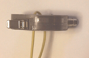
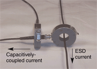
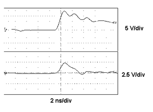
Most current probes were designed for measuring radio-frequency currents in low-impedance (50 W to 100 W) systems, which produces a significant current for a relatively low voltage. In a 50-W system, you get 1 A of current per 50 W. That much current causes magneticfields to dominate the electric fields around the cable.The conductor’s voltage can jump a few thousand volts withonly a few amperes flowing through it. Thus, electricfields can dominate magnetic fields. The electric fieldscan couple through the probes and produce measurement errors.Therefore, your current probes need very good electric fieldshielding. Figure 1 shows how to check the electric field response of a current probe using a folded-wire null experiment. Toperform the experiment, fold the wire carrying the ESD currentand insert it into the current probe until the fold is justflush with the opposite side of the probe. Then inject ESDthrough the wire. You’ll expose the inside of the probe tothe electric field on the wire but no net current flows throughthe probe. The probe’s output should read zero. I’ve seensome current probes in this configuration that produce anoutput half as great as the output produced when the current-carryingwire passes through the probe. Such a current probe isn’tparticularly useful in ESD investigations. Whenyou measure ESD currents, you’ll often measure the currentboth inside and outside your EUT’s enclosure. That dual measurementrequires two current probes. Most current probes have anamplitude accuracy of ±2 dB, which is acceptable formany EMI emissions tests in which you measure the resulton a spectrum analyzer at 10 dB/div. The ±2 dB specificationwon’t let you accurately compare the amplitude of ESD currentsfrom the two probes. For that measurement, you’ll need a pair of matchedcurrent probes. Some current probe manufacturers will provide sets of current probes with the amplitude response matched to within 1% or 2%. A manufacturer may not charge more for the matched probes, but you must remember to ask for them. Currentprobes can cause measurement errors, so you need to knowhow much error your probes contribute. Figure 2shows two current probes set up to make an error measurement.An ESD-induced current flows down the cable that passes through the current probe on the right. A second, matched current probe on the left measures the current flowing from the righthand probe. The ESD current can couple into the righthand probe through the capacitance between the probe on the right and the cable passing through it. Figure 3shows the output of the two current probes. The top waveformshows the ESD current flowing in the vertical wire as measuredby the righthand probe of Figure 2. The bottom waveform showsthe current measured by the lefthand current probe, whichis the common-mode current through the cable passing throughthe righthand probe. About 32% of the 8.5 V (or 2.75 V)—dividedby the probe’s transfer impedance—of the high-frequency currentcouples onto the probe body due to capacitance. The righthandprobe has removed current from the signal you want to measure. Only a few picofarads of capacitance can cause these effects, so you must realize that not all of the original ESD-induced current may enter the EUT. Thus, if your EUT performs better when subjected to ESD while your test equipment is connected to it, then you must measure the diverted current Nowthat you have the test equipment and you have measured anyerrors due to coupling, you can begin your investigation.I suggest you use IEC 61000-4-2 as a guide for any ESD investigation,because your product must comply with this standard in orderto bear the CE Marking, which is essential for selling electronics products in Europe. (A complete discussion of IEC 61000-4-2is beyond the scope of this article.) The standard dictatesthe number of points on your EUT that you must subject toESD. By changing the selection of test points, you can affectthe outcome of the test, because some test points may bemore susceptible to ESD interference than others. Afteryou select the test points, you’re ready to subject yoursystem to ESD. Fire the ESD simulator while you touch itsoutput electrode directly to the EUT. That’s known as a contactdischarge. IEC 61000-4-2 specifies that you must make 10discharges to each point for each of four ESD voltages youuse and for both polarities (+ and –). So the number of testpoints can significantly affect how long the test takes.For 4 voltages and 20 test points, that totals 1600 discharges(4 voltages x 20 points x 2 polarities x 10 discharges).Such a test could take an hour or more depending on how quicklyyou can position the simulator for the next discharge. And20 points is a small number; some EUTs can require many moredischarge points. For more thorough testing, you can alwaysperform more ESD testing than the standard requires, butthis will increase your test time. Here Comes the Judgment Interferencefrom ESD can enter your EUT not only from direct dischargesat the EUT’s enclosure, but also through its cables. To conducta valid ESD test, terminate an EUT’s cables in ways similarto those found in normal operation. Cable terminations affect both the differential impedance and the common-mode impedance of the cables. If your EUT connects to other equipment during actual use, then you must simulate the auxiliary equipment. You must verify that the currents flowing in the EUT’s cables are the same as those that flow in normal use. Otherwise,your test setup might alter the system’s ESD performance,and it won’t represent how the EUT will respond to real-worldESD. Ifthe impedances of the cable terminations in your test setupdiffer from those in an actual setup, they’ll most likelychange the normal ringing frequency of signals. The terminationscan dampen cable currents or change the characteristics ofthe ESD-induced current’s rising edge. Most cables will attenuate the ESD pulse’s rising-edge energy before the current reaches the end of the cable. And the cable itself will attenuatethe high-frequency components of the ESD current. So, ifyou don’t properly simulate the cable connections to yourEUT’s peripheral equipment, you won’t get the same attenuation.Less attenuation will cause more ESD energy to enter theEUT, which will cause your EUT to falsely fail an ESD test.More attenuation could result in a false failure, which meansyour EUT could be more susceptible to ESD than you realize. Shield the Cables Checkthe amount of current on the shield compared to the amountof current that enters the EUT through the cable’s connectionat the EUT. Put one current probe on the cable outside ofthe EUT. Place the second current probe on the cable or leadsfrom the cable inside the EUT. Inject an ESD pulse into thecable’s connector shield at the outside of the EUT. Use thetwo probes to see how much of the ESD-induced current inthe cable passes into the EUT. If a measurable current entersthe EUT, then the shield may not cover 360° around the cable’swires. Remember to calculate the L3dI/dt voltage drop across10 nH (about 1 cm) of conductor inside the EUT, which isa good measure of the ESD interference. If the voltage dropis large enough to degrade the EUT’s performance, then you’vemost likely found your ESD problem. Youmust take care to ensure the internal current probe doesnot bring in ESD via its own cable shield. You should groundthe cable’s shield where it enters the EUT’s metal enclosure.If the system doesn’t have a metal enclosure, you may notbe able to keep EMI currents on the probe cables from reachingcritical circuits. Sofar, I’ve discussed measurements related to a direct hitfrom ESD, but ESD can produce EMI that can radiate into anenclosure through access openings. Once inside an enclosure,the EMI radiation can couple into wires, PCB traces, andconductive cabinets, which produces unwanted current pulses.These currents can induce substantial dI/dt induced voltagesof several volts per centimeter on cables. You can test forESD coupling by discharging an ESD simulator into a metalplate placed close to the EUT. The plate will radiate EMIfrom the pulse into your system. Ultimately,your EUT’s performance determines if it passes an ESD test.You can easily spot a malfunction in some equipment. In other equipment, usually complex equipment such as a server, problems that aren’t immediately obvious may lurk after anESD event. Unfortunately, you may not detect these problemsduring the ESD test. Instead, they may occur at the customer’ssite. Youmay not be able to operate the EUT under the same conditionsas your customer. The EUT may have millions of possible operating states, and some may fail because of ESD damage while other states function properly. You may not be able to have the system in a sensitive state during the ESD test, especially since you probably won’t know beforehand which states theESD damage affects. Equipment characteristics combined withthe high-frequency effects of ESD have given rise to thebelief that ESD testing isn’t repeatable. ESD testing isa matter of cost vs. test coverage. You have to decide howmuch testing is cost effective. Giventhe nonrepeatable nature of ESD, you should test your product under conditions that go beyond the requirements of ESD test standards. So if you can, perform more discharges at more voltages than the standards require. Also, don’t rely on normal operation of the equipment as evidence of the absence of problems. If your EUT has a microprocessor or operates under PC control, then you can write diagnostic softwareto look for possible problems that can affect your customer. T&MW FOOTNOTE Doug Smithis manager of EMC at Auspex Systems, Santa Clara, CA, as well as an independent consultant. He has published dozens of technical articles and conference papers at IEEE EMC Symposia and ESD Symposia. E-Mail:doug@dsmith.org. | ||||||
|
| ||||||
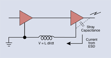
An ESD event is a voltage discharge that creates currents in circuits. Those currents can in turn produce voltages across the length of a wire or a circuit trace, and the voltage levels may surprise you. Assume a conductor has an inductance of 10 nH/cm. Therefore, the voltage induced by an ESD current along 1 cm of wire is: V = L x dI/dt The current produced by an ESD event can reach 10 A in just 1 ns. That fast rise will induce voltage of 10x10–9 x10/10–9 or 100 V/cm. The figure shows that inductance in a return path between two circuits can cause them to have different potentials relative to ground when the fast current from ESD passes through the ground path. That difference can cause a logic gate to misinterpret a bit. Significant current also can flow through small capacitances between and across circuit components and signal paths. You can calculate the current using the following equation: I = C x dV/dt Assume an ESD pulse causes a change in voltage of 1000 V in 1 ns across 5 pF of capacitance. The pulse will produce 5x10–12x1000/10–9 or 5 A of current in the circuit.—Doug Smith |


