
Address: P. O. Box 1457, Los Gatos,
CA 95031
TEL:
800-323-3956/408-356-4186
FAX:
408-358-3799
Mobile: 408-858-4528
URL:
www.dsmith.org
Email: doug@dsmith.org

Often the simplest of tools can be used to successfully track down a problem in a circuit. In the Technical Tidbit for August 1999, a magnetic field probe build from a paper clip was described. In addition to making voltage measurements in circuits, a paper clip probe can also be used to measure the relative phase or time delay between two signals. The application of this technique to impulsive signals has been made practical with the advent of relatively inexpensive, portable, and fast digitizing scopes. By measuring time delay, the location of a noise source can often be pinpointed in the circuit.
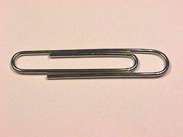
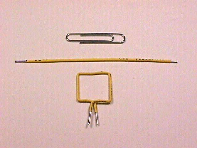
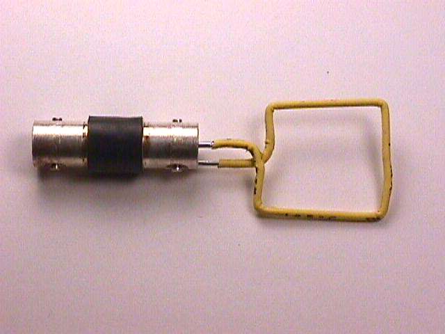
Figure 1 shows the construction of a paper clip probe. Two minutes,
some heat shrink tubing, and a pair of needle nose pliers are all that
is needed. A BNC barrel adapter makes a convenient mounting for the loop.
Being able to construct a tool quickly from available parts can be a real
advantage when time is important in an investigation.
 |
 |
|
|
Figure 1. Building a Paper Clip Probe |
||
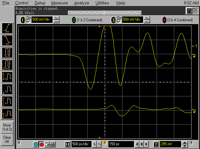
Figure 2 shows the output from an 8 GSa/sec oscilloscope connected through
two equal lengths of coaxial cable to two paper clip loops. In this case,
the purpose of the measurement was to confirm the existence of an ESD event
when an automatic tester contacted a chip. About 10 cm away was another
possible source of noise that could mimic ESD. The upper trace represents
the output of the loop held near the contacts of the tester that touch
the chip and the lower trace was from the loop held near the possible second
source of noise. Both scope inputs were terminated in 50 Ohms to match
the impedance of the coaxial cables.

Figure 2. Output from Two Paper Clip Probes
Notice that the lower signal started between 600 and 800 ps after the upper signal. That time delay corresponds approximately to the time necessary for the signal to traverse the distance between the two measurements. This measurement confirmed that the impulse was coming from contact with the chip, not from the other possible source. The amplitude difference between the two traces also leads to the same conclusion, but in many instances, amplitude differences may be not as pronounced and even unreliable because of variable coupling between the loop and the circuit.
A more general case would be tracking down a source of noise that manifestes itself as a measurable signal at some point in the circuit. The measurement could be made in any way, such as with a standard scope probe, a magnetic loop, or any other suitable sensor/probe. Two additional probes of identical time delay are placed at other points in the circuit. By analyzing the relative time delays for the three channels, the location on a printed wiring board can be determined. Determining the location of a source in three dimensional space is a little more complicated. Two algorithms for locating sources of noise (ESD events in this case) were described in two separate papers by J. Bernier and D. Lin at the 1997 EOS/ESD Symposium. The EOS/ESD Symposium is sponsored by the ESD Association.