
Address: P. O. Box 1457, Los Gatos,
CA 95031
TEL:
800-323-3956/408-356-4186
FAX:
408-358-3799
Mobile: 408-858-4528
URL:
www.dsmith.org
Email: doug@dsmith.org
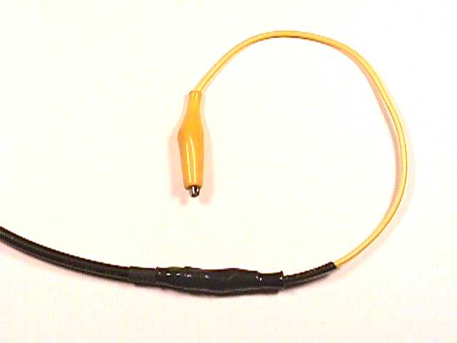
Although the object in the picture does not look like a current probe, it is. The current is measured by a resistor network covered by heat shrink tubing. Before describing how it works and its uses, let's review a simple model of a coaxial cable.
A coaxial cable can be simply modeled for this discussion in two parts for frequencies above a few hundred kilohertz. First is the cable's input impedance. If a cable with a 50 Ohm characteristic impedance is connected to a 50 Ohm load, in this case the input to a measurement instrument, then the input impedance into the opposite end of the cable is just 50 Ohms. And, everything that is happening inside the cable can be replaced, approximately, by a 50 Ohm resistor connected between where the center conductor and shield connections were. Because skin effect makes the inside surface of the shield a different world electrically than the outside surface of the shield, the outer surface of the shield must be included in our model as a thick wire. So, for the purposes of this discussion, a 50 Ohm coaxial cable can be modeled as a 50 Ohm resistor in series with a thick wire (the shield) connected to the chassis of the measuring instrument.
Now, on to the details of the resistive current probe. Figures 1 and
2 show the construction details. First the jacket of the cable is stripped
to expose the shield and the center conductor as shown in Figure 1. A 47
Ohm resistor connects the center conductor to the probe tip and five 10
Ohm resistors are connected from the tip back to the shield. The 10 Ohm
resistors should be equally spaced around the circumference of the cable
as shown in Figure 2. Carbon composition resistors are ideal for this use
if available. These resistors form a 2 Ohm resistor of reasonably low inductance.
Figure 1. Side View of Current Probe [1]
Figure 2. End View of Current Probe [1]
Figure 3 shows the equivalent circuit of the current probe. The input impedance of the coaxial cable is replaced by a 50 Ohm resistor, the 10 Ohm resistors are shown as a single 2 Ohm resistor, and the outer surface of the cable shield is shown as a wire. The junction of the 50 Ohm and 47 Ohm resistors is the node where the center conductor connects to the 47 Ohm resistor.
The circuit operates as follows. Assume one Ampere of current is flowing
from the probe tip through the resistor network to the measuring instrument
chassis on the cable shield. That current will generate approximately 2
Volts across the 2 Ohm resistor (actually 1.96 Volts if the other two resistors
are taken into account). Approximately one half of that voltage, about
1 Volt (actually 1.01 Volts), is developed across the 50 Ohm input to the
cable and delivered to the measuring instrument. Thus the transfer impedance
of this current probe is about 1 Ohm, that is it gives an output of 1 Volt
for a current of 1 Ampere. Structures of similar design have been used
to measure currents in numerous applications. One is the target used in
IEC 61000-4-2 to calibrate the current waveform of an ESD simulator.
Figure 3. Equivalent Circuit of Current Probe
In A New Type of Furniture ESD and
Its Implications, delivered at the 1993 EOS/ESD Symposium, this
probe was used to measure the induced current in a wire due to emissions
from a nearby ESD event. The one Ohm transfer impedance of the probe allows
the scope vertical scale to be converted directly from Volts to Amperes.
For this application, a wire was attached to the probe tip as shown in
Figure 4 to form an antenna. Used in this way, the probe makes a great
ESD event detector in that it gives a reading of the current flowing on
the wire as a result of EMI radiated from the ESD event.
Figure 4. Using a Resistor Current Probe to Detect and Characterize Radiation from an ESD Event [1]
But there is another use for this probe, that of finding noisy areas of ground on a circuit board or in a system. Only 10 to 20 microamps of current above 30 MHz flowing on a cable at one frequency may cause radiated emissions to exceed required class A limits. If the probe is connected to a spectrum analyzer through a high pass filter and protection network, to protect the input of the spectrum analyzer, it can be used to probe various areas of ground on a circuit board in a system. Also recommended is a 0.01 uF DC blocking cap in series with the tip, in case the tip is touched to a power node by accident. When touched to the board ground, it delivers a signal to the spectrum analyzer that is the amount of high frequency current flowing on the wire.
The probe is touched to the circuit board ground in many areas of the circuit board, especially in the neighborhood of connectors. It can even be plugged into ground pins of connectors. Anywhere on the board ground that the output of the probe exceeds a few tens of microamps at one frequency is a dangerous place to have a cable connected to. A cable attached to this point may also carry the current and cause an emissions problem. Depending on the length and what is at the end of the cable, the current may flow at a different frequency (harmonic of a system clock), but there is a real possibility of a problem.
The probe and its resistor network could be built into a test probe of the type used on multimeters for ease of use. Built with standard film resistors, the probe should work to about 300 MHz (just the region where cable radiation is usually a problem). For higher frequencies, resistors with lower inductance are needed. One approach would be to use ten 20 Ohm resistors to lower the effective inductance although resistor physical size becomes an issue.
It's not a highly accurate way of predicting emissions problems or the
best way to measure ESD events, but simple tools like this can make troubleshooting
a circuit easier. I highly recommend it be included in the lab toolbox.
[1] From A New Type of Furniture ESD and Its Implications, Douglas C. Smith, 1993 EOS/ESD Symposium Proceedings, pp. 3-7.