
Address: P. O. Box 1457, Los Gatos,
CA 95031
TEL:
800-323-3956/408-356-4186
FAX:
408-358-3799
Mobile: 408-858-4528
URL:
www.dsmith.org
Email: doug@dsmith.org

Current probes are usually used for measuring currents, so the idea of directly measuring voltage drop in a circuit with a current probe seems a little strange. But, under the right conditions, current probes do exactly that. To understand how this happens and of what use the characteristic is, it is necessary to look at how a current probe works.
The following analysis assumes that the current probe does not disturb the current flowing in the wire which is reasonable in most cases. Without this assumption, the analysis is much more complicated.
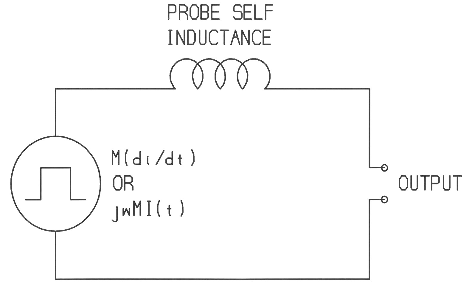
Figure 1 shows the Thevenin equivalent circuit of a current probe. The open circuit voltage is Mdi/dt (jwMI(t) in the frequency domain) and the Thevenin impedance is just the self inductance of the probe coil wound around the core. The resistance of the wire and core losses are assumed to be small to simplify the analysis. The output is usually connected by a coaxial cable to an oscilloscope or spectrum analyzer and the cable must be terminated in its characteristic impedance, usually 50 Ohms. The 50 Ohm load on the output together with the probe self inductance form a single pole L/R low pass filter.

Figure 1. Probe Equivalent Circuit
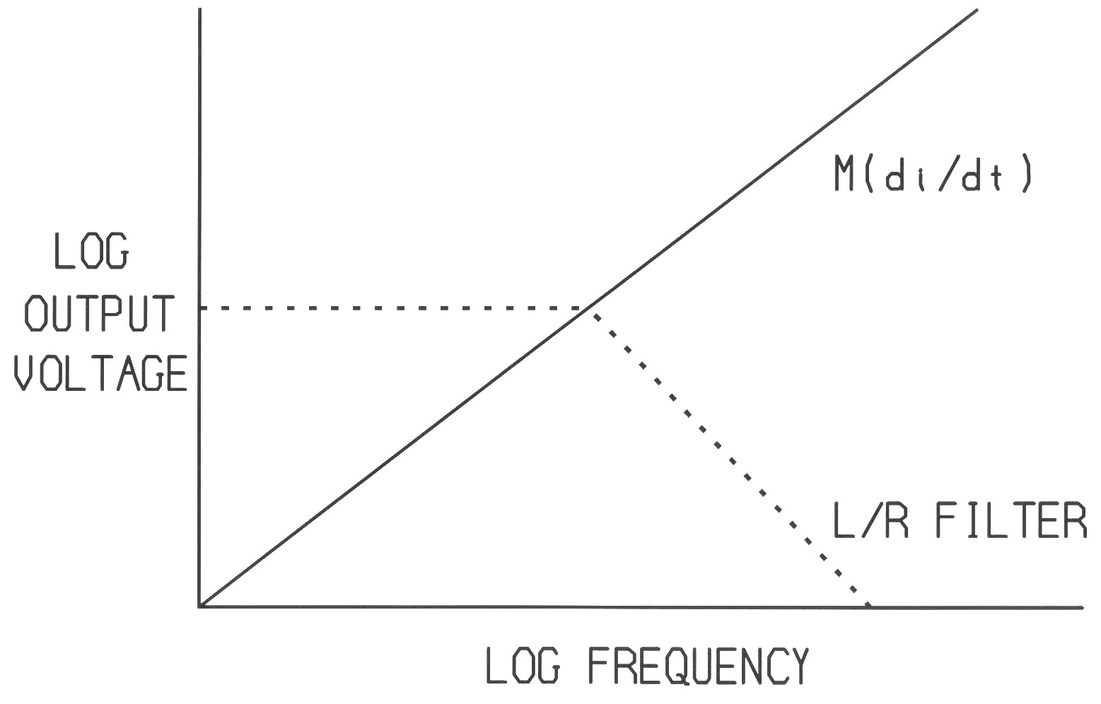
If a constant current swept in frequency passes through the probe, the Thevenin equivalent circuit of Figure 1 produces the two responses shown in Figure 2. The voltage source increases at 20 dB/decade with frequency as di/dt increases linearly with frequency for a constant current. At the frequency where the reactance of the probe coil inductance equals the load resistance, 50 Ohms, the L/R divider response decreases at 20 dB/decade.

Figure 2. Probe Frequency Response to a Constant Current
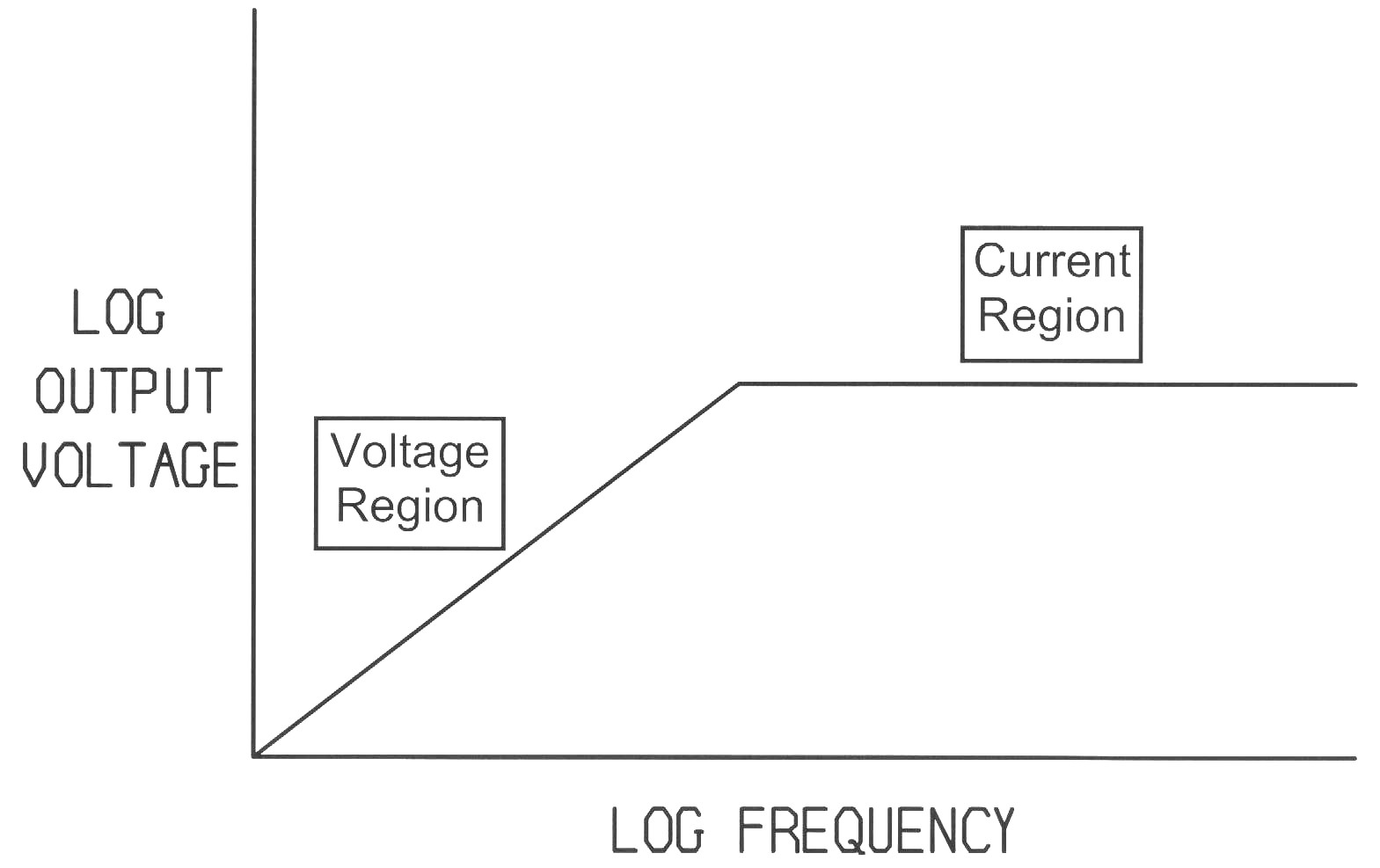
To obtain the output voltage delivered to the load, the open circuit voltage must be multiplied by the L/R divider. On a log scale that means adding the two curves. The resultant response is shown in Figure 3.

Figure 3. Net Probe Frequency Response to a Constant
Current
Most of the time, it is convenient to use the probe in the flat region of the frequency response, labeled "Current Region" in Figure 3. In this frequency region, the probe exhibits a flat transfer impedance, the ratio of output voltage to current flowing through the probe. Below this region the transfer impedance changes with frequency, making the probe inconvenient to use in the frequency domain and difficult to use on a time domain measurement such as with an oscilloscope.
Multiplying the L/R voltage divider by jwMI(t) to find the output voltage
delivered to the load and then rearranging and combining terms, the equation
for transfer impedance can be calculated as:
(1) Zt = (M/L)RLwhere:
- Zt = the transfer impedance of the probe
- M = the mutual inductance between the probe coil and the current carrying wire
- L = the inductance of the coil that is wound on the magnetic core of the probe
- RL = the load impedance on the probe, usually 50 Ohms
The corner frequency in Figures 2 and 3 can be calculated from:
(2) |XL| = |SL| = RLat f = Fc , the corner frequency
where:
- XL = the reactance of the probe coil
- L = the inductance of the probe coil
- | x | means magnitude of x
Combining equations (1) and (2), and solving for M results in:
(3)
From equation (3) one can calculate M since Zt
and Fc are known from the probe specifications.
Now the interesting part:
Remember in Figure 3 above that below Fc the output voltage of the probe is Mdi/dt, and one can calculate M from equation (3). The voltage drop across the wire carrying the current through the probe is Lwdi/dt, where Lw is the inductance of the wire which can be measured, estimated, or calculated. The output of the probe has the same waveshape (the di/dt part) as the voltage drop across the wire and differs only by a constant, M vs. Lw, from the voltage drop across the wire. If a wire has Lw nH of inductance per cm and the probe has M nH of mutual inductance, then the probe output is the voltage drop across M/Lw cm of the wire! For example, if the wire inductance is 10 nH/cm and M is 40 nH, then the probe output is the voltage drop across 4 cm of the wire.
This property is useful for estimating the voltage drop across a current carrying wire where direct voltage measurements are either not convenient or not possible such as when working with high voltages or during lightning surge testing. For more information read my paper, Current Probes, More Useful Than You Think, published at the 1998 IEEE EMC Symposium.
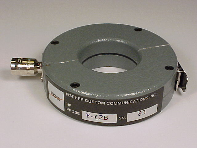
What makes the F-62B probe in the picture suited for such measurements is that its corner frequency is over 200 MHz. Thus its output is equal to Mdi/dt up to that frequency. For most probes used in current measurements one would like to have the corner frequency as low as possible. In the design of this probe, the corner frequency was made as high as possible.
As with any measurement, verify that using the probe does not affect the circuit parameters. The impedance added to the circuit by a current probe should be small compared to the circuit impedance.