
Address: P. O. Box 1457, Los Gatos,
CA 95031
TEL:
800-323-3956/408-356-4186
FAX:
408-358-3799
Mobile: 408-858-4528
URL:
www.dsmith.org
Email: doug@dsmith.org

Ferrite cores are often installed on cables to insert a common mode impedance. This is done to reduce common mode currents that cause unwanted emissions and potential failure to meet international emission regulations like CISPR 22 and FCC Part 15. Many EMC engineers have noticed the emissions at a few frequencies go up with the installation of a ferrite core in some applications. The cores usually used for this purpose are made with a lossy material and therefore the common mode impedance has a significant resistive component. Normally, one would not expect that a resonance is caused by the core tuning the cable because of the resistive part of its common mode impedance.
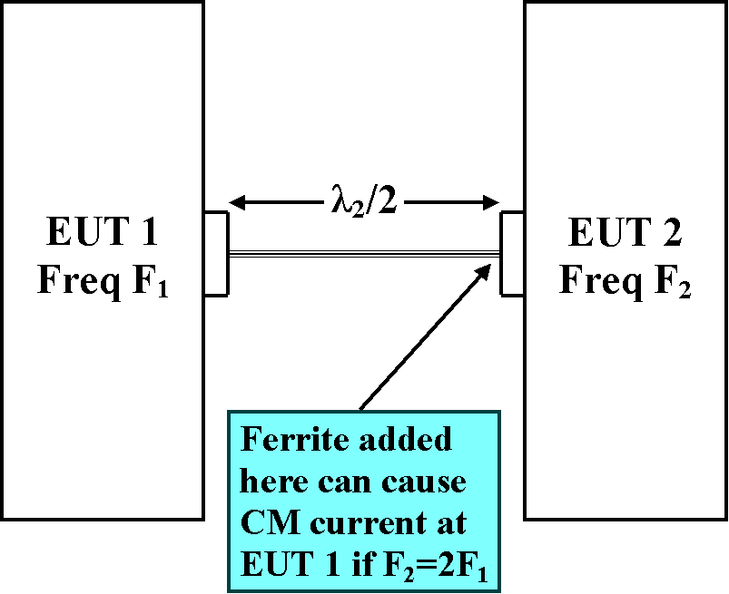
As it turns out, inserting a resistive common mode impedance on a cable can indeed cause a tuning/resonance effect to occur along with the potential for increased emissions. One way this can happen is illustrated in Figure 1 below.

Figure 1. Two Pieces of Equipment Connected via a Cable
In Figure 1, there are two pieces of equipment under test (EUT) connected by a single cable. We will assume that the equipment enclosures are made of metal and are large enough to be a significant part of a wavelength at the frequencies of interest. For instance, a personal computer enclosure would meet this criteria at 150 MHz.
EUT 1 and EUT 2 have internal circuitry such that they both can potentially radiate but the source in EUT 1 has a frequency, F1, that is one half of the frequency, F2, that is available from the source in EUT 2. The cable length that connects the two pieces of equipment is one half wavelength at F2 and therefore is one quarter wavelength at F1.
Some background is needed here. A half wavelength wire can translate a low impedance at one end to a low impedance at the other end whereas a quarter wavelength wire translates a high impedance at one end to a low impedance at the other. A quarter wavelength wire makes a good antenna where the chassis of the equipment to which the wire is fastened becomes the other half of the antenna. This is because the quarter wavelength wire, with its end in free space, presents a low impedance at the equipment end. This allows high frequency currents to flow into the wire and radiate. It only takes on the order of 20 microamps to be a potential radiated emissions problem. If the far end of the quarter wavelength wire is connected to a metal chassis instead of ending in free space, the boundary condition at the end of the wire (that it ends in free space) is not met and the impedance looking into the wire from the driven end becomes higher. This results in less common mode current flowing and radiation decreases.
The opposite occurs for a half wavelength wire. If one end is open, a high impedance is presented at the other end whereas a low impedance at one end causes the impedance presented at the other end to be lower.
Now the interesting part. Looking into the cable from EUT 2, the impedance will be low at F2 if the enclosure of EUT 1 presents a low impedance (likely) at the end of the half wavelength cable. As a result of the low impedance presented to EUT 2, current at frequency F2 will flow and radiated emission results.
Looking into the cable from EUT 1, the likely low impedance presented by the enclosure of EUT 2 will be reflected back to EUT 1 as a high impedance because the cable is a quarter of a wavelength at F1. The source of potential emission in EUT 1 cannot drive current into the high impedance at F1 so emissions at F1 will be low.
At EMC test time, the engineer notices the emission at F2 and correctly tracks it to the common mode current on the cable coming from EUT 2. In an attempt to fix the problem, the engineer installs a couple of ferrite cores on the cable at EUT 2. By inserting common mode impedance in the cable, the common mode current at F2 from EUT 2 is reduced along with the radiated emission at F2. Problem solved... except that the installation of the ferrite at EUT 2 raises the common mode impedance at the EUT 2 end of the cable. Since the cable is one quarter of a wavelength at F1, this lowers the common mode impedance at EUT 1 allowing the source there at F1 to drive more current onto the cable. This results in increased radiated emission at F1 which may now become a problem when it was not before!
In this case, putting additional common mode resistance at the EUT 2 end of the cable tuned the cable to be a good antenna at EUT 1 by isolating the enclosure of EUT 2 from the end of the cable, in a common mode sense..