Crossing Ground Plane Breaks, A Source of Crosstalk
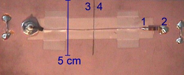
Figure 1. A path crossing a break in a ground plane

Address: P. O. Box 1457, Los Gatos,CA 95031
TEL: 800-323-3956/408-356-4186
FAX: 408-358-3799
Mobile: 408-858-4528
URL: www.dsmith.org
Email: doug@dsmith.org
Figure 1. A path crossing a break in a ground plane
EMC and signal integrity engineers know that a signal that crosses overa break in a ground plane often causes reflections as well as immunity andEMC problems. An additional problem that often results is excessive crosstalkbetween paths crossing the break. Figure 1 shows part of a circuitboard with a single path (of approximately 50 Ohms impedance) that crossesa 5 cm break in the ground plane. The path is about 10 cm in length. Theboard's solid ground plane extends downward from the bottom of the figurefor about another 10 cm. A 300 mV signal with a risetime of about 300 pswas launched on the signal path. The waveform across the 47 Ohm resistor,nodes 1 and 2, is shown in Figure 2 using 100 mV/div and 5 ns/div scale factors.
The voltage across the ground plane break at nodes 3 and 4 is shown in Figure 3. Both waveforms were taken with a Fischer Custom Communications BCP-1 differential probe. Noticethe that the peak voltage in Figure 3 is almost 100 mV. That voltage representsthe voltage drop caused by the signal's return current flowing in the groundplane through the impedance (read that "inductance") of the path around theend of the break in the ground plane. As bad as this is for radiated emissionsimagine what would happen if a second path crossed the break 1 cm above thesignal path, about halfway between the existing signal path and the topedge of the board above nodes 3 and 4.
| 100 mV/div |  | ||
| 5 ns/div | |||
| Figure 2. Signal Voltage (V1-V2) | |||
| 100 mV/Div |  | ||
| 5 ns/div | |||
| Figure 3. Slit Voltage (V3-V4) | |||
Normally, there would not be significant crosstalk between two paths spaced 1 cm apart overa ground plane. However, in this case, both paths mustshare the impedance around the end of the ground plane break in their returnpaths and thus the voltage measured across the break in Figure 3 will becoupled into the second, victim, path. For the common case of a low impedancegate output driving a high impedance gate input in the victim path, the ~80mV peak voltage of Figure 3 will show up as crosstalk between the signalpath of Figure 1 and our hypothetical victim path. In this case, the peakcrosstalk is nearly 1/3 of the original signal amplitude, not a value thatcan be ignored.
As a general rule, any paths crossing a break in a ground plane (actuallyin all the ground and power planes of a board) will likely be strongly coupledresulting in significant crosstalk. The plane breaks I have seen in someequipment are much longer that the example of Figure 1. For those cases,even signals with much slower risetime could be strongly coupled. For casesof a broken ground plane over a solid power plane, or vice versa, there mayor may not be a problem depending on several factors including plane spacing.Such a case is beyond the scope of this short Technical Tidbit.
The waveforms in this article were taken with an AgilentInfinium 54845a oscilloscope.