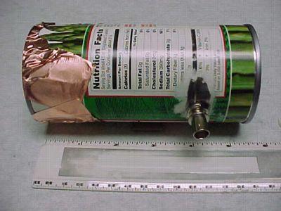
Figure 1. Can Horn Antenna - Side View

Address: P. O. Box 1457, Los Gatos,CA 95031
TEL: 800-323-3956/408-356-4186
FAX: 408-358-3799
Mobile: 408-858-4528
URL: www.dsmith.org
Email: doug@dsmith.org
Figure 1. Can Horn Antenna - Side View
Abstract: Test equipment does not always have to be expensive.A simple horn antenna made from an asparagus can is described and its useoutlined. This device has been successfully used for debugging emissionsproblems in new designs.
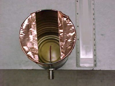
A set of cans of varying sizes (tomato paste, asparagus, etc.) can be used to cover a wide range of frequencies.
Use the can horn antenna by positioning it a few feet from an equipmentunder test (EUT). Keeping it generally pointed at the EUT, move the can aroundthe surface of an imaginary sphere enclosing the EUT, rotating the can topickup different polarizations of an emitted wave. For large EUTs, one maywant to point the antenna at various parts of the EUT from each positionon the sphere. When a signal is picked up on a receiver or spectrumanalyzer, one can move the antenna closer, following the signal. Often thesource of the emission can be resolved this way.
Note that radiated emissions at these elevated frequencies can "bounce and scatter" incomplex random interactions to the point of making the specific sourcedifficult to locate. In this situation, the "horn" antenna canbe placed directly above the suspected product area, such as gaps, seams,or gap arrays (such as finger-stock). By sliding the aperture around incontact with the product surface, the emissions can be directed into theantenna itself, increasing the resolution of the source identification.
While not exactly a "calibrated" antenna, it can find problems in the development lab simply and inexpensively.
The idea for this antenna was contributed by W.Michael King. It is based on a previous urgent needfor a probe to detect problems at these frequencies whenhe was working in a very remote location in the Andes Mountains - in 1966! Michael has beenknown to say "I looked at theconcept of the "feed horn" in our X-band parabola, and couldn'tresist the temptation to call this a "food horn." His website ishttp://www.systemsemc.com.