
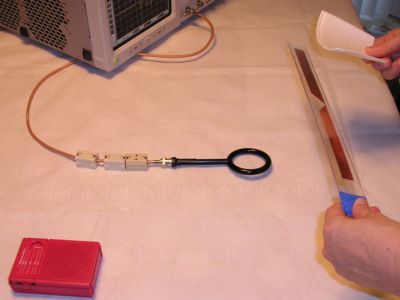
Figure 1. Magnetic Loop Used to Pickup EMI from an ESD Event
Abstract: ESD can have significant effectson electronic system operation. The effects of electric and magnetic fieldcoupling is explored using E and H field probes. Conclusions are drawn onresulting system effects and the nature of the fields.
Discussion: To gain insight into the nature of the fields radiatedfrom ESD events, measurements were made using magnetic field and electricfield probes. The source of ESD events used was the generator described onthis website in a Technical Tidbit, June 2001, A StaticField Powered EMI Source.The source is composed of two lengths of copper tape with a small gap in-between.Sparks are induced by bringing a static charge close to the copper foil.In this case, the spark gap is a fraction of a millimeter resulting in fastdi/dt with risetimes of current on the order of a couple hundred picoseconds.
Figure 1 shows the basic test setup. The AM radio in the picture is usedto indicate that the generator is actually generating sparks as evidencedby "pops" in the radio as the charged styrofoam is moved over thecopper tape. A standard 6 cm 7405 shielded loopwas used to pick up the radiated magnetic fields of the ESD event by responding(mostly) to magnetic fields (there is some electric field response, see Signal and Noise Measurement Techniques UsingMagnetic Field Probes (~600K pdf file)on this site for more information). Voltages picked up by the loop due tomagnetic fields would be comparable to that picked up by loop structuresof similar dimensions, cables for instance, in a system. The loop was connectedusing high quality RG-142B/U coaxial cable to a 50 Ohm termination in thescope. Ferrite cores were used to help isolate the shield of the cable frombecoming part of the antenna structure.
Figure 2 shows the loop output for this test setup. The importantparameter to note is the peak voltage of over 3 volts. Such interferenceis a real problem when looking for glitches with oscilloscope probes. Loopsare always formed when making voltage measurements and interference likethis easily gets into the measurement. In addition, it is easy to see howradiated fields from ESD can effect systems.
Figure 2. Loop Output from Test Setup of Figure 1
Figure 3 shows a similar measurement setup for electric fields. The probe is part of the same 7405 probe set containing the loop probe in Figure 1. The probe is essentially an insulated metal ball connected to the center conductor of the coax. The shield of the cable extends up to the ball but is not connected.The overall antenna structure has two parts: first, the ball and second,the shield as far back as the ferrite cores, an asymmetrical dipole of sorts.The RG142B/U cable connects to a 50 Ohm termination in the scope,
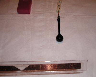
Figure 3. E-field Test Setup - Right Side
Figure 4 shows the measurement result using the ball probe. Note the amplitudeof about 2 volts, a significant amount of EMI. The ringing frequency is likely dueto a combination of the resonant frequency of the copper tape structure at about 500 MHz and the ball and cable shield antenna.
Figure 4. "Ball Probe" Response to an ESD Event
(probe on right side of event)
(probe on right side of event)
For the same movement of the charged styrofoam, but with the ball probe nearthe left hand side of the copper tape antenna as shown in Figure 5, the oppositefield is picked up by the loop. The result is shown in Figure 6. The amplitudeof the response is about the same, a peak of 2 Volts, but the polarity isreversed. For a fixed position of the ball, an opposite polarity waveformcan also be made by moving the styrofoam in the opposite direction.
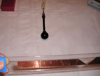
Figure 5. E-field Test Setup - Left Side
Figure 6. "Ball Probe" Response to an ESD Event
(probe on left side of event)
(probe on left side of event)
A question: The polarity of the E field probe output inverted when the probewas moved from the right side of the spark gap in the copper foil to the leftside. What happens to the output of the H field probe if it is moved thesame way? A hint can be found in a pair of Technical Tibits on this sitethat cover a completely different topic:
- February 2002, Cable Effects Part 2: InductivePickup by Cables in a System
- March 2002, Cable Effects Part 3: CapacitivePickup by Cables in a System
Additional information on this site regarding ESD effects on systems includes:
- November 1999: Transient Suppression Plane
- May 2001, Hidden Threatsto Electronic Equipment
- June 2001, A StaticField Powered EMI Source
- January 2002, Cable Effects Part 1: CableDischarge Events
- May 2002, Printed Wiring Board Coupling toa Nearby Metal Plane, Part 2: ESD Immunity
- February 2003, Crossing Ground Plane Breaks - Part 3, Immunity to Radiated EMI
- May 2003, Signal Paths Passing Through Ground and Power Planes, Effects on Immunity
- ESD Immunity in System Designs, System FieldExperiences and Effects of PWB Layout (~950K)
- (2000 EOS/ESD Symposium paper)