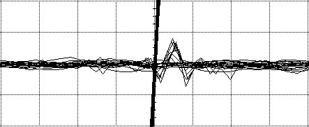
Figure 1. Inter-channel Crosstalk Example
(vertical scale = 20 mv/div - large signal)
(vertical scale = 2 mv/div - small signal)
(horizontal scale = 1 ns/div)
Abstract: Crosstalk between channels of an oscilloscope can contribute to measurement error. Conditions which can result in crosstalk error as well as signs that measurement error maybe occurring are discussed and recommendations made.
Discussion: Whenever a large signal, such as a logic signal, is displayed on a scope at the same time a small signal is also displayed on another channel, inter-channel crosstalk should be considered a potential source of error in the small signal. Figure 1 shows two traces, one a large signal and the other a much smaller signal displayed with persistence to show several traces. Sin(x)/x has been turned off to show that the speed of the signal is near the limit of the sampling rate of this scope.
In the example of Figure 1, the large signal is about 300 mV P-P with a sub-nanosecond rise time and the small signal is really just a 50 Ohm load and should be a horizontal line. An error signal is generated on the order of 2 mV P-P on the sensitive trace by crosstalk. In this case, the crosstalk was only on adjacent channels (1 and 2 but not 1 and 3) and only when the large signal was driven off screen (300 mV signal, 160 mV from top to bottom of screen). The crosstalk in Figure 1 is about 40 dB lower than the original signal, which seems reasonable. And it is, but such crosstalk can still present problems. Whenever multiple signals are delivered to a scope, each signal should be kept within the range of the screen, even if not currently being displayed.
But, some popular scopes exhibit this much crosstalk, or more, without overdriving the inputs. This can be a problem if one is looking at mixed signals, such as logic and small analog signals. If you are measuring mixed signals simultaneously, I would recommend replacing the smallest signal with a 50 Ohm load at the scope input connector and make sure what remains is very small compared to the signal to be viewed on that channel. For this test, the scope should be triggered from the large signal. This is essentially a variation of my null experiment.
Other signs that error is creeping into a scope measurement include:
- Changing the vertical scale by a factor does not change the displayed waveform by the same factor (usually 2X)
- The scope triggers when the waveform is not passing through the trigger level
Additional Material: An in-depth audio-visual format tutorial on this subject, covering background as well as more technical details, is available at: http://emcesd-p.com.
If you like the information in this article and others on this website, much more information is available in my courses. Click here to see a listing of upcoming courses on design, measurement, and troubleshooting of chips, circuits, and systems.
