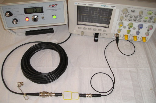
Figure 1. A 50 Ohm Series Termination Built
Abstract: A shielded series 50
Ohm termination can be a useful addition to a troubleshooting kit.
Using such a termination with a high voltage transient generator,
specifically the TG-EFT, is described. Generation of a train of pulses
using reflections or just one pulse is covered.
Discussion: Figure 1 shows the test setup used for this experiment. A Fischer Custom Communications
TG-EFT high voltage pulse generator is connected through about 10
meters (~30 feet) of 50 Ohm coaxial cable to a square wire loop covered
with heat shrink tubing. Figure 2 shows construction of the loop.
A similar second loop is connected through one meter of coax cable to an Agilent
DSO5054A oscilloscope.
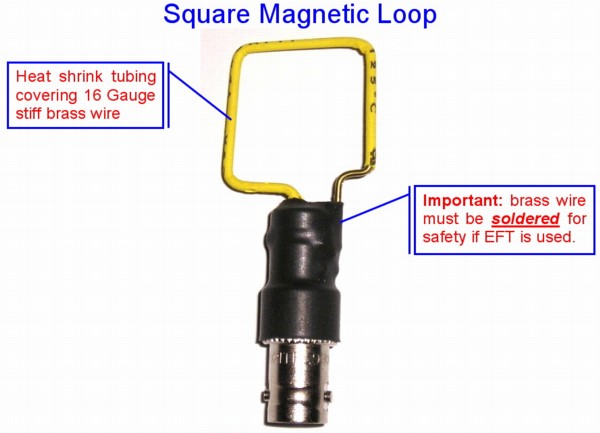
Figure 2. Close-up of Loop Construction
The resulting waveform recorded on the scope is shown in Figure 3. The waveform is Mdi/dt of the current flowing in the loop driven by the TG-EFT. For a setting of 100 Volts peak of the TG-EFT, the resulting initial pulse picked up by the second loop connected to the scope is about 4 Volts. This property is useful for injecting controlled pulses into a PCB as described in the August 2008 Technical Tidbit. However, since the output of the TG-EFT is a relatively low impedance (<50 Ohms) during and for a relatively long time after the pulse, the reflection from the loop is reflected again off of the TG-EFT and appears about 120 ns later, attenuated to about one half of its original value in Figure 3. The reflections continue until they die out.
Some of the attentenuation of the pulse is due to loss in the cable. For shorter cables, the round trip delay and the loss in the cable will be less resulting in closer spacing of the pulses and less attenuation between the pulses. A train of pulses such as shown in Figure 3, especially if a shorter cable is used, can be used to excite a failure mechanism which has a low probability of occurrence for each pulse by supplying multiple pulses. But, often just one pulse is desired. This can be achieved by adding a 50 Ohm series termination at the output of the TG-EFT.
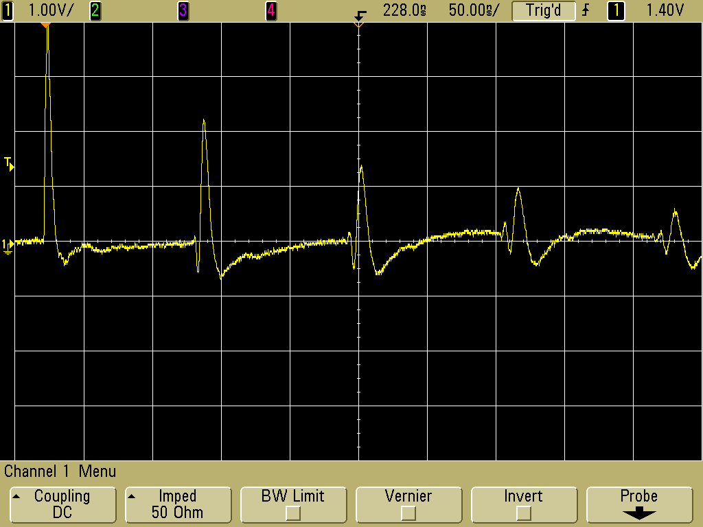
Figure 4 shows the 50 Ohm series termination used for this experiment. Its construction is described in the April 2008 Technical Tidbit on this site. Mounting of the termination at the output of the TG-EFT is shown in Figure 5.
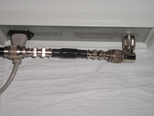
Figure 5. Termination Connected to the TG-EFT Pulse Generator
Figure 6 shows the resulting output from the second loop when the termination is used. Note that the reflections are attenuated significantly with respect to the original pulse allowing the circuit to receive a single pulse for troubleshooting. Usually the TG-EFT output is gradually increased until a response from the circuit under test occurs so the reflections in Figure 6 do not significantly affect the circuit troubleshooting.
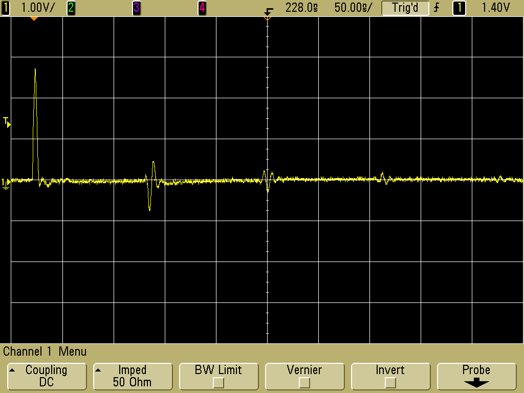
Figure 6. Waveform Induced into Second Loop With Series Termination at the Pulse Generator

Figure 2. Close-up of Loop Construction
The resulting waveform recorded on the scope is shown in Figure 3. The waveform is Mdi/dt of the current flowing in the loop driven by the TG-EFT. For a setting of 100 Volts peak of the TG-EFT, the resulting initial pulse picked up by the second loop connected to the scope is about 4 Volts. This property is useful for injecting controlled pulses into a PCB as described in the August 2008 Technical Tidbit. However, since the output of the TG-EFT is a relatively low impedance (<50 Ohms) during and for a relatively long time after the pulse, the reflection from the loop is reflected again off of the TG-EFT and appears about 120 ns later, attenuated to about one half of its original value in Figure 3. The reflections continue until they die out.
Some of the attentenuation of the pulse is due to loss in the cable. For shorter cables, the round trip delay and the loss in the cable will be less resulting in closer spacing of the pulses and less attenuation between the pulses. A train of pulses such as shown in Figure 3, especially if a shorter cable is used, can be used to excite a failure mechanism which has a low probability of occurrence for each pulse by supplying multiple pulses. But, often just one pulse is desired. This can be achieved by adding a 50 Ohm series termination at the output of the TG-EFT.

Figure 3. Waveform Induced into Second Loop
Figure 4 shows the 50 Ohm series termination used for this experiment. Its construction is described in the April 2008 Technical Tidbit on this site. Mounting of the termination at the output of the TG-EFT is shown in Figure 5.
Figure 4. 50 Ohm Shielded Series Termination

Figure 5. Termination Connected to the TG-EFT Pulse Generator
Figure 6 shows the resulting output from the second loop when the termination is used. Note that the reflections are attenuated significantly with respect to the original pulse allowing the circuit to receive a single pulse for troubleshooting. Usually the TG-EFT output is gradually increased until a response from the circuit under test occurs so the reflections in Figure 6 do not significantly affect the circuit troubleshooting.

Figure 6. Waveform Induced into Second Loop With Series Termination at the Pulse Generator
Summary:
One possible use for a series 50 Ohm Termination was shown, to modify
the output characteristics of the TG-EFT signal generator for
troubleshooting circuits. Many other uses are possible.
Additional articles on this website related to this topic are:
- March 2000, Improved Construction Technique for a 50 Ohm Termination
- August 2008, The Square Shielded Loop - Part 4, Coupling to a PCB
- April 2009, Construction of a Series 50 Ohm Termination
- Fischer Custom Communications TG-EFT high voltage pulse generator (more on this next month)
- The scope used in this Technical Tidbit is an Agilent DSO5054A, a great little scope that is easy to use and boots in 9 seconds flat!
Click here for a description of my latest seminar titled (now also available online as a WebEx seminar):
EMC
Lab Techniques for Designers
(How to find EMC problems and have some confidence your system will pass EMC testing while it is still in your lab).
(How to find EMC problems and have some confidence your system will pass EMC testing while it is still in your lab).
 |
My new website for engineers and technicians, CircuitAdvisor.com, is coming! The site will contain technews and analysis programs, cartoons, multimedia tutorials and more.The site will be open soon. |
Home

