
Abstract: Heat sinks on ICs
can be a source of emissions at high frequencies in the multi-GHz
range. A method of identifying high risk frequencies by measuring the
resonant frequencies of the heat sink tines is discussed.
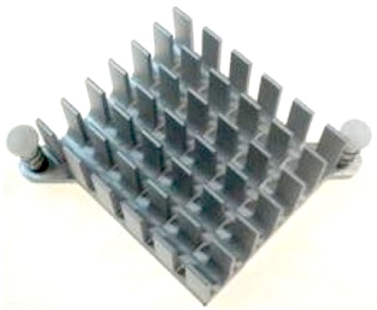
Discussion: Many heat sinks
have tines that protrude perpendicularly from a base plate such as the
one shown in Figure 1. Today's clock frequencies are so high as to be
able to excite the tines as quarter wave monopoles resulting in
something like an antenna farm on top of the IC, potentially radiating
a clock harmonic or other source resulting in an emissions problem.
One way to measure the resonant frequency of physical structures in general and heat sink tines in particular is shown in the June 2006 Technical Tidbit, Measuring Structural Resonances on this site. Basically, one would hold a very small shielded loop at the base of one of the heat sink tines to couple energy into the tine. By measuring the reflected signal from the small shielded loop, the resonant frequency of a tine can be measured as the frequency where the reflected signal experiences a dip as the tine absorbs energy from the loop. The lowest frequency this would occur at is the frequency at which the tine is 1/4 wavelength. The method is described in detail in the June 2006 article referenced above. Figure 2 shows the method being applied to a PCB test board mounted over a copper clad board. The object in that case is to measure the resonant frequency of the LC tuned circuit composed of the capacitor formed by the PCB and copper clad board, and the inductance of the short wire between them.
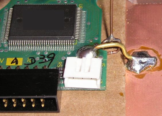
Figure 2. Use of a Small Shielded Magnetic Loop to Measure PCB-Chassis Resonance
I observed a case some years ago where 4.7 GHz was leaking out of every slot and seam in the enclosure of a product. It turned out that 4.7 GHz was the third harmonic of the processor clock. When I measured the resonant frequency of the hea tsink tines, the dip in the reflection from the loop was right at 4.7 GHz indicating the tines were 1/4 wavelength monopoles, very efficient radiators, at that frequency. If the tines had been longer or shorter the emissions problem would have been reduced significantly.
One way to measure the resonant frequency of physical structures in general and heat sink tines in particular is shown in the June 2006 Technical Tidbit, Measuring Structural Resonances on this site. Basically, one would hold a very small shielded loop at the base of one of the heat sink tines to couple energy into the tine. By measuring the reflected signal from the small shielded loop, the resonant frequency of a tine can be measured as the frequency where the reflected signal experiences a dip as the tine absorbs energy from the loop. The lowest frequency this would occur at is the frequency at which the tine is 1/4 wavelength. The method is described in detail in the June 2006 article referenced above. Figure 2 shows the method being applied to a PCB test board mounted over a copper clad board. The object in that case is to measure the resonant frequency of the LC tuned circuit composed of the capacitor formed by the PCB and copper clad board, and the inductance of the short wire between them.
Figure 2. Use of a Small Shielded Magnetic Loop to Measure PCB-Chassis Resonance
I observed a case some years ago where 4.7 GHz was leaking out of every slot and seam in the enclosure of a product. It turned out that 4.7 GHz was the third harmonic of the processor clock. When I measured the resonant frequency of the hea tsink tines, the dip in the reflection from the loop was right at 4.7 GHz indicating the tines were 1/4 wavelength monopoles, very efficient radiators, at that frequency. If the tines had been longer or shorter the emissions problem would have been reduced significantly.
Summary: Using the
simple method outlined, one can determine the resonant frequencies of
the tines on a heat sink. Knowing this information in combination with
information about the IC used allows an assessment of the risk of
emissions problems from the heat sink.
Additional articles on this website related to this topic are:
Additional articles on this website related to this topic are:
- May 2002, Printed Wiring Board Coupling to
a Nearby Metal Plane, Part 2: ESD Immunity
- June 2006, Measuring Structural Resonances
Click here to see information on my upcoming seminar in Newport Beach, CA.
Need help with a design or additional training on technical subjects? Click on the image below to go to CircuitAdvisor.com, a new engineering resource for training, news, and fun.
Need help with a design or additional training on technical subjects? Click on the image below to go to CircuitAdvisor.com, a new engineering resource for training, news, and fun.

If you like the information in this article and others on this website,
much more information is available in my courses. Click here
to see a listing of upcoming courses on design, measurement, and
troubleshooting of chips, circuits, and systems. Click here to see upcoming seminars in Newport Beach, CA.
Click here for a description of my latest seminar titled (now also available online as a WebEx seminar):
EMC
Lab Techniques for Designers
(How to find EMC problems and have some confidence your system will pass EMC testing while it is still in your lab).
(How to find EMC problems and have some confidence your system will pass EMC testing while it is still in your lab).
Home