Some RFID (radio frequency
identification) transmitters operate near 10 MHz and their antennas
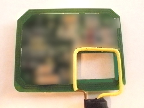
often look like that shown in Figure 1. In that figure, the RFID
transmitting antenna is composed of three turns of printed trace around
the perimeter of the PCB. The electronics on the PCB have been blurred
as they are not germane to this discussion, except to note that the
driving waveform of the RFID transmitter often has a high harmonic
content. This harmonic content can be the source of problems if one of
the harmonics fall on a self-resonance of the RFID antenna.
In Figure 1, there is a 2.5 cm/1 inch magnetic loop constructed out of
US 16 AWG stiff brass wire covered with heat shrink tubing. This loop
is being held so that a good portion of it couples into the RFID
antenna. By measuring the reflected signal of the loop over a frequency
range, driven from the tracking generator of the spectrum analyzer, we
can determine the self-resonant frequencies of the RFID antenna. This
method is described in my Technical Tidbit:
June 2006, Measuring Structural Resonances.
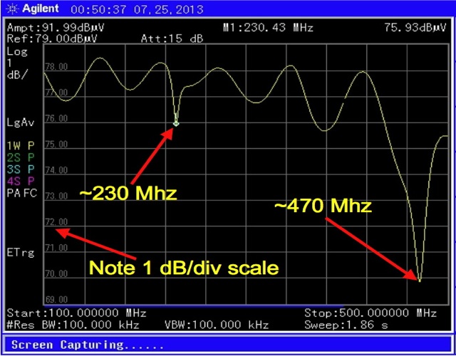
Figure 2 shows the resulting plot from the configuration of Figure 1
from 100 MHz to 500 MHz, well above the ~10 MHz intended frequency of
the RFID circuit. The plot is similar that of the reflection
coefficient of the wire loop. The smooth waves are a small impedance
mismatch somewhere in the system. But the two sharp dips represents
energy absorbed from the loop, and therefore not reflected, by the RFID
antenna. Note the vertical scale of one db/div. Such an expanded scale
is needed as the coupling from the loop into the RFID antenna is not
strong so we are looking for small changes in the reflected signal from
the loop.

Figure 2. Plot of Loop Reflected Signal from 100 to 500 MHz.
In the plot of Figure 2, one can see that there are two
self-resonant frequencies, ~230 MHz and ~470 MHz. In this case, the
resonance at ~230 MHz lined up with one of the harmonics of the RFID
signal and caused a radiated emissions problem at that frequency.
Murphy's Law in action.
For most physical structures, like RFID antennas, components,
PCBs, etc., there are self-resonant frequencies that are much higher in
frequency than one might think and often much higher than the normal
frequency of operation. These self-resonant frequencies can cause
problems, such as in this example.
Summary:
Self-resonant frequencies of physical structures can cause significant
problems in system operation. These frequencies should be measured and
analyzed to see if they may cause problems later on or are harmless.
The example above of self-resonant frequencies causing problems is just
a small bit of my new webinar (delivered in about an hour and a half
via GoToMeeting, WebEx, or Skype) titled "Electrical Resonances in
Physical Structures (Problems and Solutions for the Design Engineer).
This webinar is available for both private showing and as a public
webinar that I plan to schedule on Friday of each week for a while.
Contact me at doug@dsmith.org for details. A description and outline is
available by clicking here.
Technical Tidbit on this site describing measuring resonances:
- June 2006, Measuring Structural Resonances
Equipment used in this Technical Tidbit:
- Agilent N9340B Spectrum Analyzer, a great portable, battery operated, spectrum analyzer!


