Abstract: Special precautions
need to be taken when measuring the current of a high voltage
discharge. A specially designed target that balances insulating a
current probe from the high voltage with minimizing inductance of the
discharge path is described. Construction details are given.
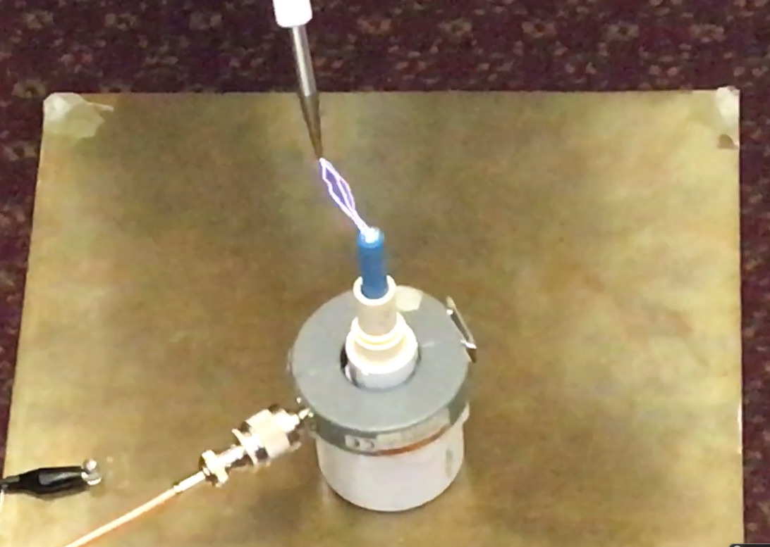
Figure 1 shows
an
overview of the target on the receiving end of multiple 50,000 Volt
discharges, mounted on a brass plate connected to earth ground. In trying to measure the discharge
current, I found it was difficult to prevent sparking over to the
current probe during my early attempts at this measurement, a more
elaborate test target was necessary. The parameters of interest were
insulation of the probe from the current path and the inductance of the
current path.
Figure 2 shows a close-up picture of the target. Its construction
consists of a 6 inch/15 cm length #10 screw (you can see the screw head
at the top of the target) inserted into a brass tube with a close fit.
The purpose of the brass tube is to reduce the inductance of the
current path due to its greater diameter and the lack of screw threads
on its surface. Skin effect will cause high frequency to have to travel
over the surface of screw threads, increasing the path inductance. Two
large washers with a center hole for a #10 screw were used on both
sides of the brass plate where the #10 screw passed through the plate.
This strengthens the fastening of the brass tube to the brass plate by
the #10 screw to avoid bending of the plate, screw, or the end of the
brass tube during lab usage.
The brass tube was then covered with four layers of heat shrink tubing
and then several plastic plumbing pieces fitted into each other were placed over the insulated brass tubing. The
bottom large plastic piece spaces up the current probe above the metal
plane, providing the required insulation against breakdown between the
plane and the current probe. The tubular upper parts of the plastic
pieces serve to center the current probe on the brass tube and to
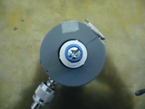
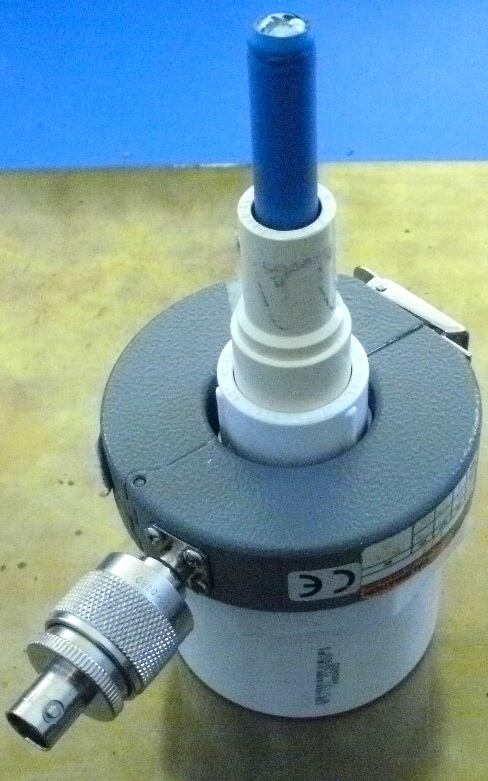
provide more insulation. This can be seen in the top view of the target
with current probe in Figure 3 and in the side view of Figure 4. The
current probe used was a Fischer Custom Communications F-65,
which is ideally suited to these kind of measurements due to its wide
bandwidth of 1 MHz to 1 GHz with flat frequency response.
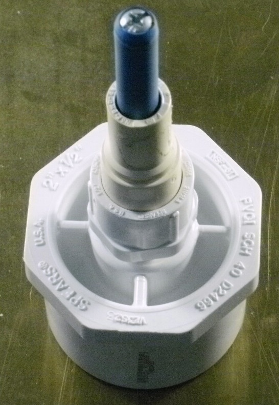
Figure 2. Close-up of Target
Figure 3. Top View of Current Probe Centered in the Target
Figure 4. Side View of Current Probe in Target
This target worked well and allowed me to take a lot of data on high
voltage discharges which will appear later this year in a published
paper and on this website in support of a new method of ESD
troubleshooting and reliably finding dangerous failure modes. The peak current of the discharges shown in Figure 1
are approximately 50 Amperes measured with a 500 MHz bandwidth.


