Magnetic Fields

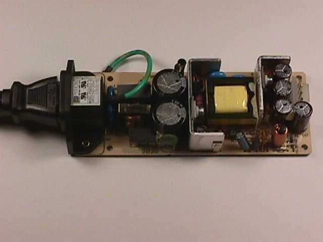
Figure 1. A Typical Switching Power Supply

Address: P. O. Box 1457, Los Gatos,
CA 95031
TEL:
800-323-3956/408-356-4186
FAX:
408-358-3799
Mobile: 408-858-4528
URL:
www.dsmith.org
Email: doug@dsmith.org

Figure 1. A Typical Switching Power Supply
Solving intermittent problems that occur in equipment can use significant engineering resources. One such source of intermittent system problems is magnetic field emission from switching power supplies. It can take quite a while for a series of 50 kHz spikes to line up with a vulnerable state in a system making for an apparent intermittent problem. Often the cause of a problem due switching power supply noise is difficult to find. Magnetic storage devices like tape drives and disk drives can be especially sensitive to the magnetic fields from a switching power supply, not to mention small analog signals such as those in optical systems and phase locked loops.
Switching power supplies are capable of generating noise in several modes. A couple of these modes can disrupt system operation by signal corruption in circuits which are not even being powered from the supply in question. This Technical Tidbit covers one of these modes, magnetic field radiation.
The strength of magnetic fields radiated from a switching power supply can be substantial. The fields from some supplies can induce series voltages of over one volt/cm due to Mdi/dt induction on conductors near the supply. This is plenty of noise to corrupt signals in those conductors. The fields can emanate from either magnetic devices such as transformers and inductors or from features on the circuit board.
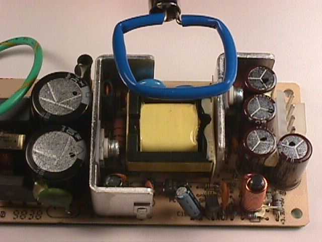
The magnetic field strength emitted from a switching power supply is not correlated with the cost or apparent quality in design of a particular power supply. The supply in Figure 1 above, an inexpensive unit (about US$20 retail), is very quiet whereas some expensive high quality supplies can be very noisy. Some power supplies have a specification on allowed magnetic field emissions in terms of the strength of the magnetic field. An equivalent approach is to define a loop geometry, such as 2 cm round or square, and an allowed peak voltage into a 50 Ohm load for a given bandwidth. A couple of hundred MHz bandwidth is usually adequate. The loop is passed over the surface of the supply, or surface of closest approach of cables or other circuits, and the peak output voltage is noted. Figure 2 shows an example of this type of measurement. The test should be done with a range of loads on the power supply.

Figure 2. Measuring Magnetic Field Emissions from a Switching Supply.
There are a few advantages of this method as opposed to specifying the magnetic field directly. One is that the result of the test gives a feeling for the amount of interference possible to nearby circuits in terms of induced voltage. Another is that instead of using an expensive calibrated field probe, it is only necessary to specify the loop geometry. Either shielded or unshielded loops can be used. The electric field shielding of shielded loops does not work well except for uniform fields or at least electric fields that are symmetric around the centerline of the loop, a condition not likely to be met for this type of testing. Most of the time I find that a simple loop made of stiff wire is adequate.
How about acceptable limits? Certainly 1 volt induced into a 2 cm loop is too high. Sooner or later a problem due to the emitted field will surface. Often, this occurs when an otherwise innocuous change is made in a nearby circuit and then the system no longer works. A limit of 50 mV into a 2 cm loop will suffice for many circuits. Systems with optical to electrical signal conversion and others with small analog signals may require even lower limits.
For more information on magnetic field probes try the links from this website listed below: