The Elusive Glitch - Part 2

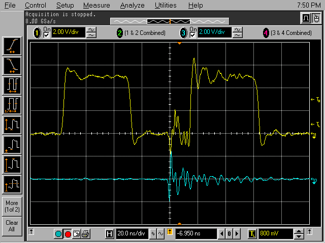
Figure 1. The Elusive Glitch

Address: P. O. Box 1457, Los Gatos,
CA 95031
TEL:
800-323-3956/408-356-4186
FAX:
408-358-3799
Mobile: 408-858-4528
URL:
www.dsmith.org
Email: doug@dsmith.org

Figure 1. The Elusive Glitch
Glitches in waveforms, such as that shown in Figure 1 above, can indicate a circuit problem or just pickup of an impulsive event nearby such as electrostatic discharge, ESD. If the glitch is the result of an event external to the circuit being probed, it can lead to wasted lab effort in tracking down the source. This is the second article on tracking down waveform glitches, the first being the Technical Tidbit for October, 2001, "The Elusive Glitch." This article describes a method of determining accurately the source of a waveform glitch.
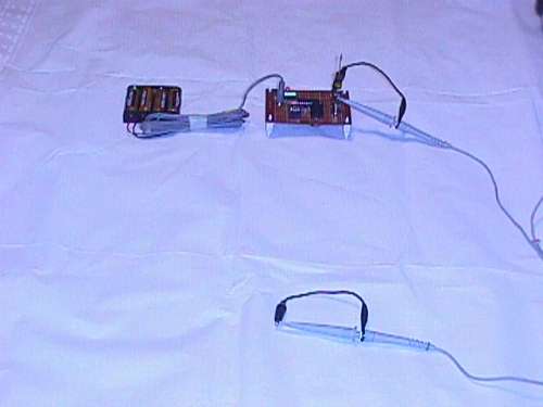
The waveforms in Figure 1 were taken with the setup shown in Figure 2. The upper waveform is the output of the oscillator whereas the lower waveform was generated by the shorted probe in the foreground of Figure 2. The shorted probe is being used as a loop antenna. Using a probe identical to the one used to measure the oscillator output has the advantage that the time delay through the two probes is identical and one can quickly evaluate the time relationships of the two waveforms. The time relationship yields information about the source of the glitch.
Just the fact that the shorted probe picked up a 2 Volt peak-to-peak glitch that is coincident with and about the same amplitude as the glitch in the signal would lead one to conclude that the source of the noise is external to the circuit. However, much more information is available about the source of the glitch..

Figure 2. Scope Setup with Extra Probe to Capture Glitch
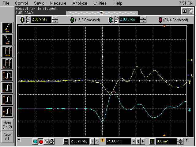
Figure 3 shows the waveforms of Figure 1 expanded from 20 ns/div to 2 ns/div. At this resolution, one can see that the shorted probe picked up its signal about one nanosecond before the probe measuring the oscillator output. This means that the shorted probe is about 30 cm (1 foot) closer to the source (in free space the speed of light is about 1 foot/ns) than the signal measuring probe. This confirms that the source of the glitch is external to the circuit. For this experiment, the source is described in A Static Field Powered EMI Source from the June, 2001 Technical Tidbit. It was located about 1 meter closer to the camera than the shorted probe in Figure 2. The scope was sampling at 8 GSa/sec and can therefore resolve distances of about 4 cm (1/8 foot).

Figure 3. Expanded Scope Display from Setup of Figure 2
One way to more accurately pinpoint the source of the noise is as follows: Arrange three shorted probes equally spaced around a circle of about 1 meter in diameter enclosing the measurement probe. If a glitch has its source external to the circuit and in the plane of the circle of probes, the arrival time at the shorted probes can be used to determine the direction the interference is coming from. Note that if the source is directly above or below the probe circle, the arrival time at the three shorted probes will be the same. By carefully examining the arrival time of the glitch at the three shorted probes, the direction of the source can be determined.
Another effect can be seen in Figure 1. Note that the second rising edge is followed by ringing that does not occur after the first rising edge. This is the impulse response of the probe and circuit to the radiated EMI glitch. Sometimes such a response can be as much of a problem as the original glitch in terms of degrading circuit performance. In this case, the impulse response is of comparable amplitude to the glitch, but with considerably lower frequency components.
For more information see:
More detailed information about this and other topics on this website is available from this site's new subscription service (to start this Fall) and seminars.