Using Mutual Inductance to Measure Voltage Drop in Circuits
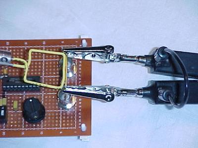
Figure 1. Measuring Drop Across the Inductance of a Wire Directly
and Through Mutual Inductance

Address: P. O. Box 1457, Los Gatos,
CA 95031
TEL:
800-323-3956/408-356-4186
FAX:
408-358-3799
Mobile: 408-858-4528
URL:
www.dsmith.org
Email: doug@dsmith.org
Figure 1. Measuring Drop Across the Inductance of a Wire Directly
and Through Mutual Inductance
Mutual inductance can be used to measure voltage drop in circuits. Several articles on this website have shown or described such uses. More specific details and conditions which can affect this type of measurement are described in this article.
Measuring voltage drops with a magnetic loop can have distinct advantages where direct connection to the circuit is not possible or desirable. One such case would be where the circuit to be measured is sitting at a high DC potential with respect to the measurement ground so the isolation of the magnetic loop is critical. Another case would be a sensitive circuit. The proximity of a magnetic loop is less of a disturbance to the measured circuit that a direct connection of most voltage probes.
In the test setup of Figure 1, the voltage across a short piece of wire
is measured by a differential probe and a magnetic loop made of stiff wire
(a paper clip). Figure 2 shows a different angle of the test setup. A low
frequency square wave at at frequency of about 14 MHz with risetime of
just under 2 ns is passed from the output of the oscillator through the
short wire and into the oscillator signal ground (shell of the right-hand
BNC connector). The chip is an HC240 with a series 50 Ohm resistor between
its output and the center pin of the left-hand BNC in Figure 2.
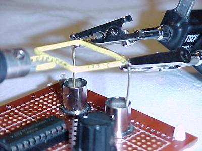
Figure 2. Close-up of Measurement Setup
The differential probe measures L·di/dt while the magnetic loop output is M·di/dt. The corresponding outputs are shown in Figure 3. The upper trace is the output of the differential probe at 250 mV/div and the lower trace is the output of the loop into 50 Ohms at 100 mV/div. The differential probe has an attenuation factor of 50:1 so the signal at the oscilloscope is only a few millivolts. As a result, the upper trace of Figure 3 can be seen to have a small amount of digitizing noise on the signal. The horizontal scale is 20 ns/div.
For this measurement, M is about 40% of L or a little less than about 10 nH. A mutual inductance this high compared to the inductance of the wire is about as much as can be expected in real measurements. Even though the differential probe and the magnetic loop have similar outputs, there is more to this measurement than meets the eye.
Figure 3. Output From Differential Probe (upper) and Magnetic Loop
(lower)
All voltage measurements must form a loop. With reference to Figure 1, the differential probe loop consists of the wire being measured, the probe tips and the connection between the probe heads (small length of wire at the right side of the picture). The measurement loop of the magnetic loop is just itself. Note that the loop size of the magnetic loop is smaller that the loop formed by the differential probe. If the measurement were of a gate output where the voltage is not an L·di/dt drop with its associated magnetic field, the loop size would not be as important as it is here.
In the measurement described here, the larger loop of the differential probe could pick up more flux from the current flowing in the wire and measure more voltage by Faraday's Law, which says the voltage induced around a loop is proportional to the time changing magnetic flux passing through the loop. If the differential probe's loop is made much smaller, the measured voltage would also get smaller as less flux from the signal current in the wire would be captured by the differential probe's loop. In this case, the magnetic loop is large enough to capture most of the flux and the larger differential probe loop does not capture much more so the two measurements are comparable. The output of the magnetic loop is smaller primarily because of magnetic flux leaking between the signal wire and magnetic loop. If the loop size of the either measurement became much smaller than the magnetic loop, the indicated voltage would be lower even though the current in the wire has not changed. In effect, the measurement loop, either that of the magnetic loop or the differential probe, determines the measured voltage. But loop size has another effect.
Notice the magnetic loop output on the lower trace appears slightly slower than the output of the differential probe. The reason is the bandwidth of the two measurements. The magnetic loop has a bandwidth determined by the voltage divider composed of its self inductance (about 80 nH) and the 50 Ohm load of the coax connecting the loop to the 50 Ohm input impedance of the oscilloscope. This divider has a corner frequency of about 100 MHz and is filtering out the higher order harmonics of the oscillator output which has a spectral bandwidth of 150 to 200 MHz (1/PiTr). The larger loop size of the differential measurement does not limit the bandwidth of that measurement because the input impedance of the differential probe is about 1500 ohms, much larger that the 50 Ohm load on the magnetic loop. Even though the inductance of the differential probe's loop is certainly larger than the inductance of the magnetic loop, the load impedance presented by the differential probe on its loop is 30 times the 50 Ohm load on the magnetic loop and so does not affect this measurement. The differential probe itself has a bandwidth of about 500 MHz.
I highly recommend reading the paper Signal and Noise Measurement Techniques Using Magnetic Field Probes (~600K) on this site for more detailed information on magnetic field probes and how they work.
Articles on this website containing information on magnetic field probes and their uses include:
Much more information on this effect and issues discussed in the other Technical Tidbits is presented in my public and private seminars.