 High Frequency MeasurementsWeb Page
Douglas C. Smith Address: P. O. Box 1457, Los Gatos,CA 95031
TEL: 800-323-3956/408-356-4186
FAX: 408-358-3799
Mobile: 408-858-4528
URL: www.dsmith.org
Email: doug@dsmith.org
Technical Tidbit - October 2003
Heisenberg and Signal Measurements
(A variation on the Uncertainty Principle)
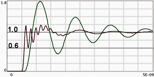
Figure 1. Actual Node Voltage (red on left) and Probe Response (green, delayed) Without Damping Resistor
(vertical scale = 0.2 Volt/div)
(horizontal scale = 500 ps/div)
Abstract: Heisenberg's Uncertainty Principle might be adapted inthe context of signal measurements to say that one cannot measure a voltageat a node without affecting it. Simulation data is presented to show thatunder realistic conditions, active probes without damping resistors can significantlyaffect the signal to be measured. The result can be more serious than justsignal loading.
Discussion: Probing a signal at a node in a circuit can have significant effects that can go beyond simple loading effects. Thisis especially true at today's faster signal rates and frequencies. Althougha probe can be checked against a known waveform to see its impulse response,a more difficult task is to determine the probe's affects on the originalsignal. For this task, computer simulations of the probe and circuit canlend insight into how the signal may be changed by the scope probe.
Active probes before about 2 years ago had a mostly capacitiveinput impedance, generally one picofarad or less. The problem is that eventhat capacitance forms a resonant circuit and causes measurement error andcircuit loading. Recently, active probe designs use a damping resistor on theorder of 100 to 200 Ohms in series with the probe tip. This lowers the Q of the tuned circuit consistingof the probe capacitance and the inductance of the probe connections andcircuit being measured. Using MI-SUGAR (Spice with a graphical interfacerunning on Mac OS X) and a model of an active probe published by the manufacturer,simulations were performed to see how use of the damping resistor affectsthe probe's interaction with the circuit to be measured.
Figure 1 shows simulation results of probe response (delayed signalin green) and the actual voltage at the measured node (red on left) fora 1 Volt source having an impedance of 25 Ohms in series with 5 nH without the probe damping resistor.The source resistance was chosen to represent a gate output resistance and the inductanceto represent nominal package inductance. Many modern chip packages have signalpath inductances ranging from 2 to 8 nH*. The risetime of the applied step is 100 ps.
The probe model used in the spice simulation is a manufacturer's multi-element model of a 4 GHz active probe fitted with a 5 cm extension adapter that included a damping resistor at the tip of about 200 Ohms. The simulation modeled theprobe's connections and input circuitry, but not the probe amplifier responsefor simplicity. For the plots in Figure 1, the damping resistor was removed.Without the damping resistor, the probe's input impedance and response issimilar to active probe designs that do not include a damping resistor. Theprobe response has a familiar overshoot and ringing that is common with evenshort probe connections on many active probes. In this case the probe responseovershoots 80% to 1.8 volts and rings just under 1 GHz for several cycles.The probe response in Figure 1 agrees well with measured results on activeprobes without damping resistors, thus helping to verify the simulation results.
However, the important detail in Figure 1 is the actual signal on thenode during the measurement, the red trace starting on the left. With the25 Ohm+5nH signal source used in the simulation, the node voltage fellto a value of about 0.6 Volt, low enough to possibly cause signal integrityproblems. Both the peak-to-peak amplitude and the period of the fast oscillationsare sensitive to the amount of source inductance, but even a few nH of inductancecan be a problem. Of course, the node voltage cannot be observed on a realcircuit because it is changed by probing it, but the simulation suggestsa real possibility of problems caused by an active probe without a dampingresistor at the tip.
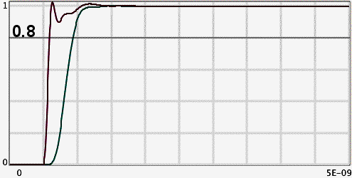
Figure 2 shows the probe response (delayed green trace) and node voltage(red trace starting to left) when the ~200 Ohm damping resistor was presentin the circuit. There is no overshoot in the probe response and the nodevoltage was much better behaved, dipping only about 10% and not exhibitingany ringing. Notice that the risetime of the probe response is about 300ps, more indicative of a 1 GHz bandwidth than the 4 GHz bandwidth the probeactually is capable of. This is due to the inductance of the 5 cm probe extension.Although the damping resistor can remove the overshoot and ringing as wellas reduce effects in the measured circuit, it cannot restore bandwidth lostdue to inductance in the probe connections. Probe connections should be keptas short as possible for this reason and other reasons. That being said, the waveforms inFigure 2 are very good compared to those in Figure 1. Onlypassive probes can achieve better performance in terms of tolerance to probeconnection inductance.
Figure 2. Actual Node Voltage (red on left) and Probe Response (green, delayed) With Damping Resistor
(vertical scale = 0.2 Volt/div)
(horizontal scale = 500 ps/div)
Summary and Conclusion: Active probes, or any type of scope probefor that matter, can have significant effects on the measured signal thatare quite distinct from the response of the probe itself. Heisenberg's principlereinvented! Active probes should always have damping resistance either
builtin or added and probe connections should be kept as short as possible. Thesedays, that means very short indeed.
Other articles on this website covering probing effects include:
Equipment used in this article includes:
- Mac OS X (FreeBSD "Unix") running on a dual G4 MacIntosh computer
- MI-SUGAR circuit simulation program for Mac OS X (Spice with a graphical interface, free!) Click hereto download the program for Mac OS X - not available for Windows. If youwould like more information on MI-SUGAR, click here to send email to Berk Ozer, the program's author.
* Inductance numbers from a private conversation with Michael King.
Top of page
Home
Questions or suggestions? Contact me at doug@dsmith.orgCopyright © 2003 Douglas C. Smith


