
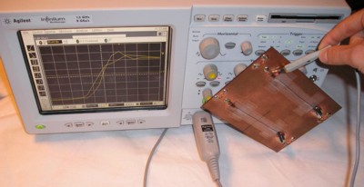
Figure 1. Test Setup for Measuring Effect of Ground Plane Break
Abstract: Signals that cross ground
plane breaks on printed wiring boards (PWBs) experience degradation as
well as cause EMI problems. Significant degradation of signal risetime
is shown to occur, even with
a relatively small ground break of five cm at risetimes on the order
of 300 ps.
Discussion: Signals crossing ground/power plane breaks can cause all sorts of problems including radiated EMI, lack of immunity to EMI, crosstalk, and degradation of the signal risetime. These effects are due mostly to the loop formed by the signal's returning current having to find its way around the plane break. The effect on signal risetime, is the subject of this article.
Figure 1 shows the test setup used to generate the data for this article. A 300 ps risetime signal from a test generator in the oscilloscope is fed directly through a BNC coupler to the test board containing two paths ending in terminations. The paths have a characteristic impedance of approximately 50 Ohms. One path stays over continuous ground while the second path crosses a five cm plane break at the middle of the break. Both paths are about 12 cm in length. The board is connected directly to the generator output as shown in Figure 2 to get the fastest risetime signal possible applied to the board, in this case about 300 ps. A picture of the board itself is shown in Figure 3.
The board is copper clad on both sides and the plane break is cut into both sides of the board. The board simulates a 4 layer board with a plane break that is cut through both the power and ground planes. 24 gauge telephone wire is held to the board using tape and approximates a 50 Ohm transmission line.
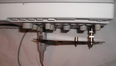
Figure 2. Detail of Board Connection to Scope Generator Output
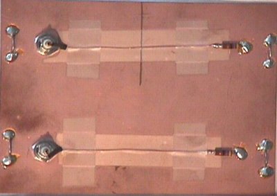
Figure 3. Test Board

The reason for the slower edge rate for the path that crosses the break is that the signal's return path in the ground plane is forced to go around the edge of the break as shown in my January, 2003 Technical Tidbit. One way to think about this for small plane breaks is that the break opens up a loop between the signal and its return path and the inductance of that loop filters out the higher frequencies of the signal. One can also think of the impedance discontinuity of the signal passing over the break as reflecting the higher frequencies of the signal back to the generator.
In Figure 4, the Sin(x)/x interpolation function of the scope is turned on to make estimating the edge rates easier. For comparison, Figure 5 shows the same waveform with Sin(x)/x interpolation turned off. One can arrive at the same conclusion from Figure 5, but since the signal is bandwidth limited to about the bandwidth of the scope, the Sin(x)/x interpolation can improve the accuracy of analysis. If the signal has components in excess of the scope bandwidth, Sin(x)/x interpolation can hide the fact that the signal is severely under sampled. For this reason I do not use Sin(x)/x interpolation unless I know the signal's bandwidth is comparable to that of the scope, as it is for this test. My August and September, 2003 Technical Tidbit articles have more information on Sin(x)/x interpolation.
Summary: The data presented shows another serious effect of allowing a signal to cross a plane break on a PWB. At the 300 ps risetimes and the five cm break used in this example, the edge rate of the signal is substantially slowed by the plane break to about two thirds of the signal staying over continuous ground.
Discussion: Signals crossing ground/power plane breaks can cause all sorts of problems including radiated EMI, lack of immunity to EMI, crosstalk, and degradation of the signal risetime. These effects are due mostly to the loop formed by the signal's returning current having to find its way around the plane break. The effect on signal risetime, is the subject of this article.
Figure 1 shows the test setup used to generate the data for this article. A 300 ps risetime signal from a test generator in the oscilloscope is fed directly through a BNC coupler to the test board containing two paths ending in terminations. The paths have a characteristic impedance of approximately 50 Ohms. One path stays over continuous ground while the second path crosses a five cm plane break at the middle of the break. Both paths are about 12 cm in length. The board is connected directly to the generator output as shown in Figure 2 to get the fastest risetime signal possible applied to the board, in this case about 300 ps. A picture of the board itself is shown in Figure 3.
The board is copper clad on both sides and the plane break is cut into both sides of the board. The board simulates a 4 layer board with a plane break that is cut through both the power and ground planes. 24 gauge telephone wire is held to the board using tape and approximates a 50 Ohm transmission line.
Figure 2. Detail of Board Connection to Scope Generator Output
Figure 3. Test Board
Figure 4 shows the rising edges of the
signals as measured at the terminations for both paths at 200 ps/div. The path over
continuous ground shows a significantly faster edge rate (about 50% faster) and slight
overshoot while the path that passes over the plane break is slower and
the overshoot is filtered out. This is a significant effect considering that many
boards containing plane breaks have breaks that are much longer than the five cm one used
in this test.
Figure 4. Comparison of the Two Signals at the Terminations
The reason for the slower edge rate for the path that crosses the break is that the signal's return path in the ground plane is forced to go around the edge of the break as shown in my January, 2003 Technical Tidbit. One way to think about this for small plane breaks is that the break opens up a loop between the signal and its return path and the inductance of that loop filters out the higher frequencies of the signal. One can also think of the impedance discontinuity of the signal passing over the break as reflecting the higher frequencies of the signal back to the generator.
In Figure 4, the Sin(x)/x interpolation function of the scope is turned on to make estimating the edge rates easier. For comparison, Figure 5 shows the same waveform with Sin(x)/x interpolation turned off. One can arrive at the same conclusion from Figure 5, but since the signal is bandwidth limited to about the bandwidth of the scope, the Sin(x)/x interpolation can improve the accuracy of analysis. If the signal has components in excess of the scope bandwidth, Sin(x)/x interpolation can hide the fact that the signal is severely under sampled. For this reason I do not use Sin(x)/x interpolation unless I know the signal's bandwidth is comparable to that of the scope, as it is for this test. My August and September, 2003 Technical Tidbit articles have more information on Sin(x)/x interpolation.
Figure 5. The Signals of Figure 4 with Sin(x)/x Interpolation Turned Off
Summary: The data presented shows another serious effect of allowing a signal to cross a plane break on a PWB. At the 300 ps risetimes and the five cm break used in this example, the edge rate of the signal is substantially slowed by the plane break to about two thirds of the signal staying over continuous ground.
Other articles on this website related to this topic are:
- December 2002, Crossing Ground Plane Breaks, A Source of Crosstalk
- January 2003, Crossing Ground Plane Breaks - Part 2, Tracing Current Paths
- February 2003, Crossing Ground Plane Breaks - Part 3, Immunity to Radiated EMI
- August 2003, Sin(x)/x, The Forgotten Setting - Part One
- September 2003, Sin(x)/x, The Forgotten Setting - Part Two, An EMI Example
Additional Material: An in-depth audio-visual format tutorial on this subject, covering background as well as more technical details, is available at: http://emcesd-p.com.
If you like the information in this article and others on this website, much more information is available in my courses. Click here to see a listing of upcoming courses on design, measurement, and troubleshooting of chips, circuits, and systems.
Equipment used in this article includes:
Top of page
Home