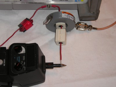
Figure 1. Test Setup Using Two Ferrite Chokes
Abstract: Ferrite chokes are often
used to reduce currents due to ESD and to provide
series impedance to suppress common mode currents that can cause EMC
emissions problems. Data is presented to show how an ESD current is
affected by single pass and multiple turn ferrite chokes. The data is
extended
to predict how the chokes affect EMC emissions. Recommendations are
inferred from the data as to when to use single pass or multiple turn
windings on ferrite cores.
Discussion: When ferrite cores, sometimes called ferrite chokes, are used to insert an impedance in series with a conductor, the question of using a single pass through the ferrite core or using multiple turns often comes up. Multiple turns ideally would result in increased impedance, a desired outcome. However, inter-turn capacitance and other high frequency effects may cause a reduction of the series impedance and other problems. Data was taken using an ESD waveform to analyze performance of single and multiple turn ferrite chokes. An ESD waveform is ideal for this purpose since it contains both high and low frequency components as well as significant current that might cause core saturation in some cases.
Figure 1 shows the test setup for evaluating multiple, six in this case, turns on a ferrite core compared to a single pass through two ferrite cores. A Fischer F-65 current probe is used for the current measurements. With its one Ohm transfer impedance (one Volt output into 50 Ohms for one Ampere of current through the probe) and one Mhz to one GHz flat frequency response, this probe is ideal for measuring ESD currents.
The output of the ESD simulator shown in Figure 1 is being applied to the wire passing once through two ferrite cores of the type commonly used in EMC work. These cores have an impedance that looks something like a 150 Ohm resistor in parallel with an inductor having an R/L corner frequency of a few tens of MHz with the 150 Ohm resistor. A multiple turn ferrite is shown pushed out of the way on the left.
Figure 2 shows the ESD simulator applying the ESD pulse to the wire with the six turn ferrite. The ESD was also applied to the wire on the right with no ferrite cores to generate a baseline for the ESD waveform. In all cases, a screw on the back panel of the oscilloscope chassis was used as the "ground." The ESD simulator was used without the normal IEC contact discharge tip that limits the initial rise to about 1 nanosecond. Used in this way as shown in the Figures, with just a straight, pointed metal tip, the ESD current has a risetime of about 350 picoseconds. I like to use the simulator this way to get a wider bandwidth current pulse. A generator setting of 800 Volts was used for the test.
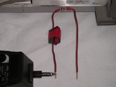
Figure 2. Test Setup Using a Ferrite Choke with Six Turn Winding
Figure 3 shows the current through the wire with no ferrite core, on the right in Figure 2. The wave shape is similar to the one described in IEC 61000-4-2 except for a second peak and other lumps on the waveform as well as the faster risetime. The extra structure is due to the shape of the oscilloscope chassis and its wired connections.
Notice the waveform is an average of 16 triggers. This was done to minimize EMI pickup because of the close range of the ESD to the scope. The EMI manifests itself as the small noise just before the rising edge. The averaging function minimizes its amplitude without affecting the display of the ESD current which is very repeatable.
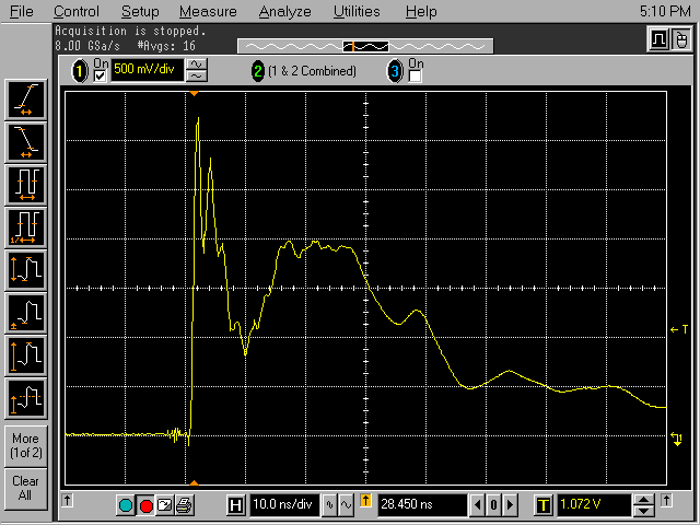
The current through two ferrites as shown in Figure 1 appears in Figure 4. The fast initial peak is reduced to about half of its original value, but the lower frequency part of the waveform, the "hump" after the peak, is only slightly reduced although somewhat smoothed compared to Figure 3. As expected, the ferrite cores used provide more effect on the high frequency content of the waveform than the low frequency content.
The fast parts of the waveform are usually associated with equipment upset because the larger di/dt in those parts of the waveform generates greater voltages that can corrupt signals. The lower frequency parts of the waveform contain most of the energy and are often responsible for physical damage to system components although the high peak current of the initial peak can sometimes cause burnout as well. So it appears that the two ferrites of Figure 1 may help with equipment upset but not so much with damage to a system.
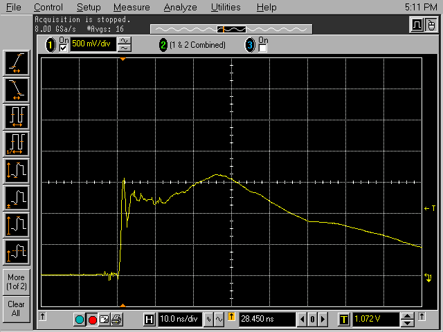
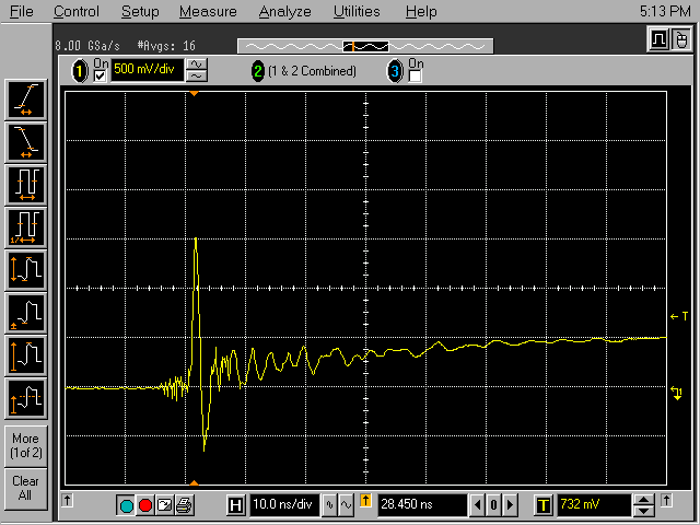
Figure 5 shows the current through the six turn ferrite core. Note there is significant reduction of the low frequency components of the current implying a reduction of the possibility of equipment damage. However, the initial peak value of 1.5 Amperes is no better than for the two ferrite, single turn case of Figure 4. Note also that the peak-to-peak amplitude of the fast spike in Figure 5 is about one third larger than for the two ferrite single pass case, two Amperes in Figure 5 instead of one and a half Amperes in Figure 4. So, the possibility of equipment upset is likely not much improved over the two ferrite case. Additional turns would likely cause an increase of the initial peak because of increased inter-turn capacitance.
There are other problems starting to surface in Figure 5 though. Notice there is ringing on the waveform indicating a resonance at about 350 MHz. This may cause problems in some applications. The resonance may also be partially responsible for the negative dip below ground, current reversal, in the waveform. The implication of the current reversal is that equipment upset that may have only occurred on one polarity of an ESD event may now, in some cases, occur on both polarities.
Think about the effect of putting one or two single turn ferrites in series with the six turn ferrite. Do you think the performance would be good at both high and low frequencies? The answer to this and generating the waveform to prove it is left as an exercise for the reader.
One can easily extend these results to continuous signals. High frequency, about 50 to 100 MHz and higher, currents are likely reduced more by single turn ferrite chokes whereas low frequency signals, below 10 MHz, are definitely reduced more by multiple turn ferrite chokes. The exact frequencies depend on the ferrite material used and circuit impedances where the ferrites are applied.
Summary: The data presented shows that single turn ferrite chokes can be effective at reducing the high frequency parts of an ESD current, likely improving the system upset response to ESD. Multiple turn ferrite chokes are more effective on the low frequency parts of the ESD current and may help avoid system damage. These results are easily extended to continuous signals.
Discussion: When ferrite cores, sometimes called ferrite chokes, are used to insert an impedance in series with a conductor, the question of using a single pass through the ferrite core or using multiple turns often comes up. Multiple turns ideally would result in increased impedance, a desired outcome. However, inter-turn capacitance and other high frequency effects may cause a reduction of the series impedance and other problems. Data was taken using an ESD waveform to analyze performance of single and multiple turn ferrite chokes. An ESD waveform is ideal for this purpose since it contains both high and low frequency components as well as significant current that might cause core saturation in some cases.
Figure 1 shows the test setup for evaluating multiple, six in this case, turns on a ferrite core compared to a single pass through two ferrite cores. A Fischer F-65 current probe is used for the current measurements. With its one Ohm transfer impedance (one Volt output into 50 Ohms for one Ampere of current through the probe) and one Mhz to one GHz flat frequency response, this probe is ideal for measuring ESD currents.
The output of the ESD simulator shown in Figure 1 is being applied to the wire passing once through two ferrite cores of the type commonly used in EMC work. These cores have an impedance that looks something like a 150 Ohm resistor in parallel with an inductor having an R/L corner frequency of a few tens of MHz with the 150 Ohm resistor. A multiple turn ferrite is shown pushed out of the way on the left.
Figure 2 shows the ESD simulator applying the ESD pulse to the wire with the six turn ferrite. The ESD was also applied to the wire on the right with no ferrite cores to generate a baseline for the ESD waveform. In all cases, a screw on the back panel of the oscilloscope chassis was used as the "ground." The ESD simulator was used without the normal IEC contact discharge tip that limits the initial rise to about 1 nanosecond. Used in this way as shown in the Figures, with just a straight, pointed metal tip, the ESD current has a risetime of about 350 picoseconds. I like to use the simulator this way to get a wider bandwidth current pulse. A generator setting of 800 Volts was used for the test.

Figure 2. Test Setup Using a Ferrite Choke with Six Turn Winding
Figure 3 shows the current through the wire with no ferrite core, on the right in Figure 2. The wave shape is similar to the one described in IEC 61000-4-2 except for a second peak and other lumps on the waveform as well as the faster risetime. The extra structure is due to the shape of the oscilloscope chassis and its wired connections.
Notice the waveform is an average of 16 triggers. This was done to minimize EMI pickup because of the close range of the ESD to the scope. The EMI manifests itself as the small noise just before the rising edge. The averaging function minimizes its amplitude without affecting the display of the ESD current which is very repeatable.

Figure 3. Current Through Solid Wire
(Vertical scale = 500 mA/division)
(Vertical scale = 500 mA/division)
The current through two ferrites as shown in Figure 1 appears in Figure 4. The fast initial peak is reduced to about half of its original value, but the lower frequency part of the waveform, the "hump" after the peak, is only slightly reduced although somewhat smoothed compared to Figure 3. As expected, the ferrite cores used provide more effect on the high frequency content of the waveform than the low frequency content.
The fast parts of the waveform are usually associated with equipment upset because the larger di/dt in those parts of the waveform generates greater voltages that can corrupt signals. The lower frequency parts of the waveform contain most of the energy and are often responsible for physical damage to system components although the high peak current of the initial peak can sometimes cause burnout as well. So it appears that the two ferrites of Figure 1 may help with equipment upset but not so much with damage to a system.

Figure 4. Current Through Two Single Turn Ferrite Chokes
(Vertical scale = 500 mA/division)
(Vertical scale = 500 mA/division)
Figure 5 shows the current through the six turn ferrite core. Note there is significant reduction of the low frequency components of the current implying a reduction of the possibility of equipment damage. However, the initial peak value of 1.5 Amperes is no better than for the two ferrite, single turn case of Figure 4. Note also that the peak-to-peak amplitude of the fast spike in Figure 5 is about one third larger than for the two ferrite single pass case, two Amperes in Figure 5 instead of one and a half Amperes in Figure 4. So, the possibility of equipment upset is likely not much improved over the two ferrite case. Additional turns would likely cause an increase of the initial peak because of increased inter-turn capacitance.
There are other problems starting to surface in Figure 5 though. Notice there is ringing on the waveform indicating a resonance at about 350 MHz. This may cause problems in some applications. The resonance may also be partially responsible for the negative dip below ground, current reversal, in the waveform. The implication of the current reversal is that equipment upset that may have only occurred on one polarity of an ESD event may now, in some cases, occur on both polarities.

Figure 5. Current Through a Ferrite Choke with Six Turn Winding
(Vertical scale = 500 mA/division)
(Vertical scale = 500 mA/division)
Think about the effect of putting one or two single turn ferrites in series with the six turn ferrite. Do you think the performance would be good at both high and low frequencies? The answer to this and generating the waveform to prove it is left as an exercise for the reader.
One can easily extend these results to continuous signals. High frequency, about 50 to 100 MHz and higher, currents are likely reduced more by single turn ferrite chokes whereas low frequency signals, below 10 MHz, are definitely reduced more by multiple turn ferrite chokes. The exact frequencies depend on the ferrite material used and circuit impedances where the ferrites are applied.
Summary: The data presented shows that single turn ferrite chokes can be effective at reducing the high frequency parts of an ESD current, likely improving the system upset response to ESD. Multiple turn ferrite chokes are more effective on the low frequency parts of the ESD current and may help avoid system damage. These results are easily extended to continuous signals.
Other articles on this website related to this topic are:
- November 1999: Transient Suppression Plane
- December 1999: Can Ferrite Cores Increase Emissions?
- May 2000, Measuring Inductor Performance
- July 2005, Radiated Interference to High Frequency Signal Measurements from the Signal Source
If you like the information in this article and others on this website, much more information is available in my courses. Click here to see a listing of upcoming courses on design, measurement, and troubleshooting of chips, circuits, and systems.
Available now for private on-site delivery and as a public seminar: my new one day seminar titled: Failure Analysis and Prevention in Electronic Circuits (Design Troubleshooting for the Lab and Field).
Equipment used in this article includes:
Top of page
Home
