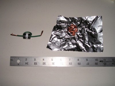
Figure 1. Components Used to Filter a Contact Discharge
Abstract: Contact discharge is used in ESD
testing to improve test repeatability, yet air discharge can have
significantly different characteristics at higher voltages. A test
method is described that uses a modified contact discharge to
simulate the characteristics of an air discharge for some important cases but with improved
repeatability.
Figure 3 shows a ~1 kV contact discharge of an ESD simulator, a KeyTek MiniZap, through a Fischer Custom Communications F-65 current probe into a ground plane to measure the discharge current waveform. The MiniZap shown is not fitted with its IEC tip so the rising edge of the current spike will be somewhat faster than the 700 ps called for in the IEC standard. Figure 4 shows the resulting current waveform. Only 1 kV was used to keep the waveform on the scope screen without having to use external attenuators on the scope. The waveform at 8 kV will be the same, just eight times larger.
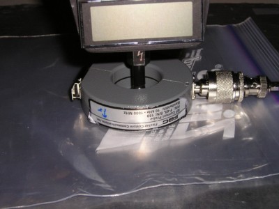
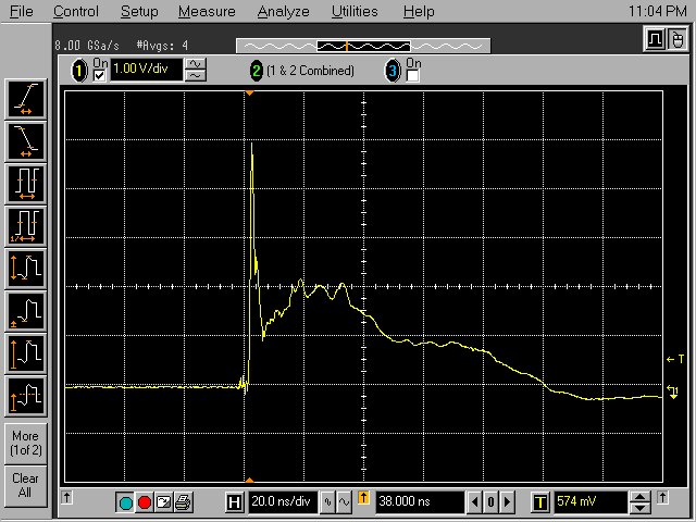
Figure 5 shows the contact discharge being applied through a filter composed of a free space capacitor made of aluminum foil mounted on the ESD simulator and the ferrite choke from Figure 1. The ferrite choke removes the initial current spike, but its characteristics are chosen so as not to affect the slower parts of the waveform. The free space capacitance of the aluminum foil slows the initial risetime to about 5 nanoseconds. The aluminum foil is not a good choice for real testing as it does not keep its shape. A compact disc sized piece of metal of just enough thickness to keep its shape and be able to be pressed onto the tip of the ESD simulator would be preferred. A CD covered with aluminum foil should work as well. The ferrite core used was a Steward part number HFB170070-100 (~140KB pdf file) core.
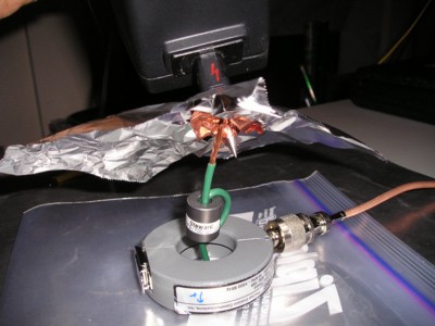
Figure 5. Contact Discharge Through "Filter" to Simulate an 8 kV Air Discharge
Figure 6 shows the resulting waveform when the filter is used. Note that the low frequency part of the waveform is not changed much whereas the initial peak is removed and the initial risetime is about 5 nanoseconds. The waveform shown in Figure 6 (multipled by eight for an 8 kV discharge) may be a good average for what one might expect of an 8 kV air discharge to an IC using an IEC 61000-4-2 complaint simulator if the IC was grounded on one or more pins to a ground plane through a low inductance connection.
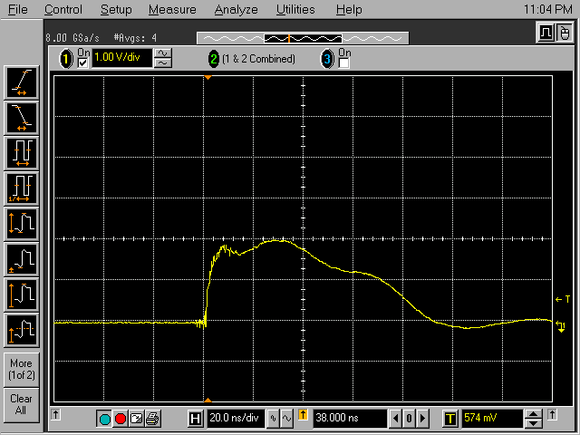
Figure 6. Resulting Current Waveform from Setup of Figure 5
(Vertical scale = 1 Amp/div)
By applying the filter to a standard IEC 61000-4-2 ESD simulator, a pretty good approximation to a slow air discharge can be generated without the inherent variability of a real air discharge. Designing a device or system to survive this waveform may help insure adequate performance at the lowest cost. This may be a very useful technique when IEC 61000-4-2 is applied to devices.
At voltages higher than 8 kV, the leading edge of the current waveform can become even slower. To apply the same technique to higher voltages, the metal free space capacitor and possibly the ferrite core will need to be modified. One can imagine, folding the free space capacitor metal around the end of the ESD simulator body to provide a more convenient form factor.
There is another use for a filtered contact discharge. If a system fails ESD testing using contact discharge, filtering the applied contact discharge as above can determine whether the system is sensitive to the low or high frequency components of the ESD waveform. This knowledge may be useful in troubleshooting the system.
Summary:A technique is shown for generating an equivalent 8 kV or higher "air" discharge to an IC or other device with sharp edges and slow approach speeds by applying filtering to a contact discharge ESD simulator. This method produces a waveform that is close to a such an air discharge and can be reproduced from test to test. A filtered contact discharge can also be useful in troubleshooting system level ESD problems by discovering whether the high or low frequency components of the ESD waveform cause the problem.
Discussion: For ESD testing using contact discharge, the discharge occurs in a vacuum relay without
the variability that air molecules, speed of approach, and other
factors cause in real air discharges. Normally such air discharges can exhibit significant
variability from discharge to discharge, especially above 4 kV. For this reason, ESD test
standards such as IEC 61000-4-2 have long used contact discharge to
improve the test repeatability, an important parameter for a test that
has legal significance. A problem arises though at higher voltages
where the discharge current of an ESD event in air can have significantly
different characteristics than contact discharge, especially for some important cases discussed below. Figure 1 shows two
"components" that can help solve this problem.
Contact discharge has the same current waveform at all voltages, including a fast rising edge (700 to 1000 ps) to a peak current of 3.75 Amps/kV followed by a longer duration (several tens of nanoseconds) discharge of the human body. Figure 2 shows the current waveform abstracted from IEC 61000-4-2 (some elements of the figure have been removed from the original which is available from the IEC). This current is measured by a special calibration target specified in the standard.
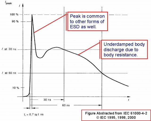
Figure 2. Current Waveform Abstracted from IEC 61000-4-2
(some elements of the picture have been removed and comments have been added))
IEC 61000-4-2 specifies that contact discharge is used whenever the discharge is to metal. Air discharge is only used when metal is not exposed, such as with a small plastic enclosure. However, some pressure has been building in the last few years to use IEC 61000-4-2 to test solid state devices such as ICs, even at 8 kV and higher, and since the device contacts are exposed metal, contact discharge is used for repeatability.
The problem is that the fast initial spike of contact discharge is less likely to occur in air at 8 kV and higher from small parts with sharp edges (IC pins) and relatively slow approach speeds consistent with handling devices. The actual characteristics of a spark are a function of arc length. The longer the arc length, the generally slower the rising edge. Sharp edges and slow approach speeds lead to longer arc lengths and these conditions are likely present for ESD occurring to devices. See this paper (~676 kB pdf file) by David Pommerenke for details on arc length effects on ESD characteristics.
So testing a device using an 8 kV contact discharge will subject the device to a current spike that is unlikely to happen in real use and may cause useless protection to be added to the device increasing its cost. How can one get repeatable air discharge testing at 8 kV for small devices? I present one possible solution below.
Contact discharge has the same current waveform at all voltages, including a fast rising edge (700 to 1000 ps) to a peak current of 3.75 Amps/kV followed by a longer duration (several tens of nanoseconds) discharge of the human body. Figure 2 shows the current waveform abstracted from IEC 61000-4-2 (some elements of the figure have been removed from the original which is available from the IEC). This current is measured by a special calibration target specified in the standard.

Figure 2. Current Waveform Abstracted from IEC 61000-4-2
(some elements of the picture have been removed and comments have been added))
IEC 61000-4-2 specifies that contact discharge is used whenever the discharge is to metal. Air discharge is only used when metal is not exposed, such as with a small plastic enclosure. However, some pressure has been building in the last few years to use IEC 61000-4-2 to test solid state devices such as ICs, even at 8 kV and higher, and since the device contacts are exposed metal, contact discharge is used for repeatability.
The problem is that the fast initial spike of contact discharge is less likely to occur in air at 8 kV and higher from small parts with sharp edges (IC pins) and relatively slow approach speeds consistent with handling devices. The actual characteristics of a spark are a function of arc length. The longer the arc length, the generally slower the rising edge. Sharp edges and slow approach speeds lead to longer arc lengths and these conditions are likely present for ESD occurring to devices. See this paper (~676 kB pdf file) by David Pommerenke for details on arc length effects on ESD characteristics.
So testing a device using an 8 kV contact discharge will subject the device to a current spike that is unlikely to happen in real use and may cause useless protection to be added to the device increasing its cost. How can one get repeatable air discharge testing at 8 kV for small devices? I present one possible solution below.
Figure 3 shows a ~1 kV contact discharge of an ESD simulator, a KeyTek MiniZap, through a Fischer Custom Communications F-65 current probe into a ground plane to measure the discharge current waveform. The MiniZap shown is not fitted with its IEC tip so the rising edge of the current spike will be somewhat faster than the 700 ps called for in the IEC standard. Figure 4 shows the resulting current waveform. Only 1 kV was used to keep the waveform on the scope screen without having to use external attenuators on the scope. The waveform at 8 kV will be the same, just eight times larger.

Figure 3. Contact Discharge Through an F-65 Current Probe

Figure 4. Current Waveform Resulting from Setup in Figure 3
(Vertical scale = 1 Amp/div)
(Vertical scale = 1 Amp/div)
Figure 5 shows the contact discharge being applied through a filter composed of a free space capacitor made of aluminum foil mounted on the ESD simulator and the ferrite choke from Figure 1. The ferrite choke removes the initial current spike, but its characteristics are chosen so as not to affect the slower parts of the waveform. The free space capacitance of the aluminum foil slows the initial risetime to about 5 nanoseconds. The aluminum foil is not a good choice for real testing as it does not keep its shape. A compact disc sized piece of metal of just enough thickness to keep its shape and be able to be pressed onto the tip of the ESD simulator would be preferred. A CD covered with aluminum foil should work as well. The ferrite core used was a Steward part number HFB170070-100 (~140KB pdf file) core.

Figure 5. Contact Discharge Through "Filter" to Simulate an 8 kV Air Discharge
Figure 6 shows the resulting waveform when the filter is used. Note that the low frequency part of the waveform is not changed much whereas the initial peak is removed and the initial risetime is about 5 nanoseconds. The waveform shown in Figure 6 (multipled by eight for an 8 kV discharge) may be a good average for what one might expect of an 8 kV air discharge to an IC using an IEC 61000-4-2 complaint simulator if the IC was grounded on one or more pins to a ground plane through a low inductance connection.

Figure 6. Resulting Current Waveform from Setup of Figure 5
(Vertical scale = 1 Amp/div)
By applying the filter to a standard IEC 61000-4-2 ESD simulator, a pretty good approximation to a slow air discharge can be generated without the inherent variability of a real air discharge. Designing a device or system to survive this waveform may help insure adequate performance at the lowest cost. This may be a very useful technique when IEC 61000-4-2 is applied to devices.
At voltages higher than 8 kV, the leading edge of the current waveform can become even slower. To apply the same technique to higher voltages, the metal free space capacitor and possibly the ferrite core will need to be modified. One can imagine, folding the free space capacitor metal around the end of the ESD simulator body to provide a more convenient form factor.
There is another use for a filtered contact discharge. If a system fails ESD testing using contact discharge, filtering the applied contact discharge as above can determine whether the system is sensitive to the low or high frequency components of the ESD waveform. This knowledge may be useful in troubleshooting the system.
Summary:A technique is shown for generating an equivalent 8 kV or higher "air" discharge to an IC or other device with sharp edges and slow approach speeds by applying filtering to a contact discharge ESD simulator. This method produces a waveform that is close to a such an air discharge and can be reproduced from test to test. A filtered contact discharge can also be useful in troubleshooting system level ESD problems by discovering whether the high or low frequency components of the ESD waveform cause the problem.
Other articles on this website related to this topic are:
- September 2005, Multiple Turn and Single-turn Ferrite Chokes Compared
- November 1999: Transient Suppression Plane
- Current Probes, More Useful Than You Think (~170K)
- (1998 IEEE EMC Symposium paper)
- IEC 61000-4-2
- KeyTek MiniZap ESD Simulator
- Fischer Custom Communications
- Steward Ferrites
- HFB170070-100: Steward ferrite core used in this article
- On the Influence of the Speed of Approach, Humidity, and Arc Length on ESD Breakdown, a 1993 paper by David Pommerenke (~676 kB pdf file)
Click here for a description of my latest seminar to be available in the Fall titled:
EMC
Lab Techniques for Designers
(How to find EMC problems and have some confidence your system will pass EMC testing while it is still in your lab).
(How to find EMC problems and have some confidence your system will pass EMC testing while it is still in your lab).
Home

