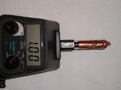
Figure 1. ESD Simulator Fitted With High Pass Filter
Abstract: High pass filtering of an ESD
contact discharge can be used for troubleshooting ESD problems
with equipment or simulating ESD from small metal objects in a
repeatable way. A method is described for constructing a simple coaxial
capacitor to provide a high pass filter that leaves just the initial
peak of the hand-metal ESD waveform while attenuating the low frequency
components.
The capacitor composed of the the simulator tip and copper foil is charged by the simulator with each ESD event. The specific simulator used here, the KeyTek MiniZap, has a leakage path after the discharge that will discharge the tip-foil capacitor as long as the foil has a conductive path back to the simulator ground connection. One needs to provide a few seconds to allow this to happen. Figure 5 illustrates using a static meter to see how fast the charge is drained from the simulator tip after a contact discharge with the tip floating. For the MiniZap, two or three seconds is more than adequate. One can check to see if enough time is allowed between discharges by measuring the discharge current into a grounded target. If the charge on the tip-foil capacitor is not drained between discharges, the discharge current will be reduced. Allow enough time between discharges to get the maximum current. Some ESD simulator designs may require a high valued high voltage resistor be built into the tip-foil capacitor to discharge it between ESD events.
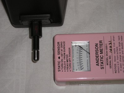
Figure 6 shows a ~1 kV contact discharge of the MiniZap ESD simulator fitted with the high pass filter through a Fischer Custom Communications F-65 current probe into a ground plane to measure the discharge current waveform. The MiniZap shown is not fitted with its IEC tip so the rising edge of the initial current spike will be somewhat faster than the 700 ps called for in the IEC standard. In this case, the current risetime is about 300 to 400 picoseconds. Figure 7 shows the resulting current waveform. The current has a peak of about three Amperes and a duration of a little less than two nanoseconds. Only 1 kV was used to keep the waveform on the scope screen without having to use external attenuators on the scope. The waveform at 8 kV will be the same, just eight times larger.
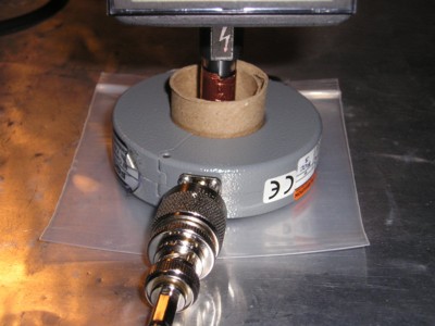
Figure 6. Contact Discharge Through "High Pass Filter" and Fischer F-65 Current Probe
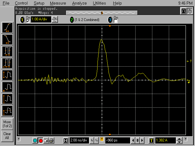
Figure 7. Resulting Current Waveform from Setup of Figure 5
(Vertical scale = 1 Amp/div)
Contrast the current waveform in Figure 7 using the high pass filter to that in Figure 8 with the filter removed. In Figure 8, from last month's Technical Tidbit, one can see not only the initial spike, but also the much longer duration body wave that follows.
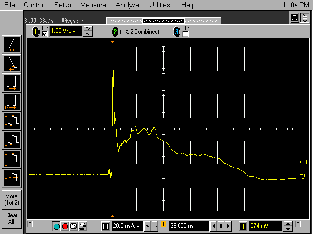
Figure 7. Resulting Current Waveform from Setup of Figure 5 Without High Pass Filter
(Vertical scale = 1 Amp/div)
By filtering out the low or high frequency components of a contact discharge ESD current, useful information can be obtained for troubleshooting equipment problems. If the problem is due to the fast spike, different mechanisms are likely to be at play than if the problem is caused by the lower frequency components of the waveform. Also high pass filtering of the ESD current can be used to simulate ESD events from relatively small pieces of metal in a repeatable way. In some ways, the current waveform of a high pass filtered contact discharge is like a Charged Device Model (~260K pdf file) test.
Summary: A method of high pass filtering an ESD simulator output is described using an easy to build coaxial capacitor. The resulting short pulse of current can be used for troubleshooting circuits and systems as well as to simulate ESD events from relatively small pieces of metal. The current pulse is in some ways similar to the current generated in a Charged Device Model ESD event.
Discussion: Last month's Technical Tidbit for September 2006 described how to low pass filter the contact discharge ESD current from an IEC 61000-4-2ESD
simulator to approximate a high voltage air discharge ESD event as well
as for
troubleshooting designs. This month, high pass filtering of the IEC
contact discharge ESD current is discussed both for troubleshooting as
well as simulating a
class of ESD events as before. In this case, the high pass filter
leaves just the initial spike of the contact discharge by attenuating
the
lower frequency components that comprise the "body wave" that lasts for
several tens of nanoseconds after the initial spike.
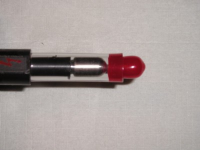
Figure 1 shows an ESD simulator with the finished filter installed. The visible copper foil is in fact one of the plates of a coaxial capacitor formed by the air discharge tip of the simulator and the copper foil. Figure 2 shows a short length of plastic tubing with a small PVC cap plugging the end. The PVC plug is in fact a vacuum port cover for an automobile intake manifold obtained from an auto parts store. The tube and plug form the dielectric of our coaxial capacitor.
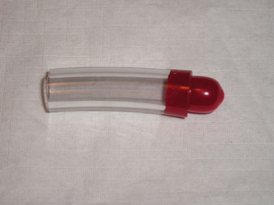
Figure 2. Plastic Tube and PVC Cap Dielectric for Coaxial Capacitor
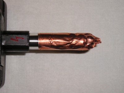
Figure 3 shows the dielectric assembly installed over the air discharge tip of the ESD simulator. In Figure 4, the copper foil tape is added. The capacitance between the ESD simulator tip and the copper foil couples only the initial spike of the ESD current waveform to the intended target.
Figure 1 shows an ESD simulator with the finished filter installed. The visible copper foil is in fact one of the plates of a coaxial capacitor formed by the air discharge tip of the simulator and the copper foil. Figure 2 shows a short length of plastic tubing with a small PVC cap plugging the end. The PVC plug is in fact a vacuum port cover for an automobile intake manifold obtained from an auto parts store. The tube and plug form the dielectric of our coaxial capacitor.

Figure 2. Plastic Tube and PVC Cap Dielectric for Coaxial Capacitor
Figure 3 shows the dielectric assembly installed over the air discharge tip of the ESD simulator. In Figure 4, the copper foil tape is added. The capacitance between the ESD simulator tip and the copper foil couples only the initial spike of the ESD current waveform to the intended target.

Figure 3. Dielectric for Coaxial Capacitor Fitted on ESD Simulator Tip

Figure 4. Tip With Insulation Wrapped in Copper Foil to Form a Capacitor
The capacitor composed of the the simulator tip and copper foil is charged by the simulator with each ESD event. The specific simulator used here, the KeyTek MiniZap, has a leakage path after the discharge that will discharge the tip-foil capacitor as long as the foil has a conductive path back to the simulator ground connection. One needs to provide a few seconds to allow this to happen. Figure 5 illustrates using a static meter to see how fast the charge is drained from the simulator tip after a contact discharge with the tip floating. For the MiniZap, two or three seconds is more than adequate. One can check to see if enough time is allowed between discharges by measuring the discharge current into a grounded target. If the charge on the tip-foil capacitor is not drained between discharges, the discharge current will be reduced. Allow enough time between discharges to get the maximum current. Some ESD simulator designs may require a high valued high voltage resistor be built into the tip-foil capacitor to discharge it between ESD events.

Figure 5. Checking Static Charge on the Simulator Tip
Figure 6 shows a ~1 kV contact discharge of the MiniZap ESD simulator fitted with the high pass filter through a Fischer Custom Communications F-65 current probe into a ground plane to measure the discharge current waveform. The MiniZap shown is not fitted with its IEC tip so the rising edge of the initial current spike will be somewhat faster than the 700 ps called for in the IEC standard. In this case, the current risetime is about 300 to 400 picoseconds. Figure 7 shows the resulting current waveform. The current has a peak of about three Amperes and a duration of a little less than two nanoseconds. Only 1 kV was used to keep the waveform on the scope screen without having to use external attenuators on the scope. The waveform at 8 kV will be the same, just eight times larger.

Figure 6. Contact Discharge Through "High Pass Filter" and Fischer F-65 Current Probe

Figure 7. Resulting Current Waveform from Setup of Figure 5
(Vertical scale = 1 Amp/div)
Contrast the current waveform in Figure 7 using the high pass filter to that in Figure 8 with the filter removed. In Figure 8, from last month's Technical Tidbit, one can see not only the initial spike, but also the much longer duration body wave that follows.

Figure 7. Resulting Current Waveform from Setup of Figure 5 Without High Pass Filter
(Vertical scale = 1 Amp/div)
By filtering out the low or high frequency components of a contact discharge ESD current, useful information can be obtained for troubleshooting equipment problems. If the problem is due to the fast spike, different mechanisms are likely to be at play than if the problem is caused by the lower frequency components of the waveform. Also high pass filtering of the ESD current can be used to simulate ESD events from relatively small pieces of metal in a repeatable way. In some ways, the current waveform of a high pass filtered contact discharge is like a Charged Device Model (~260K pdf file) test.
Summary: A method of high pass filtering an ESD simulator output is described using an easy to build coaxial capacitor. The resulting short pulse of current can be used for troubleshooting circuits and systems as well as to simulate ESD events from relatively small pieces of metal. The current pulse is in some ways similar to the current generated in a Charged Device Model ESD event.
Other articles on this website related to this topic are:
- September 2000 Technical Tidbit, Copper Foil Tape, Anyone?
- September 2006 Technical Tidbit (low pass filtering of a contact discharge waveform)
- Current Probes, More Useful Than You Think (~170K pdf file)
- (1998 IEEE EMC Symposium paper)
- IEC 61000-4-2
- KeyTek MiniZap ESD Simulator
- Fischer Custom Communications
- JEDEC Charged Device Model (~260K pdf file)
Click here for a description of my latest seminar to be available in the Fall titled:
EMC
Lab Techniques for Designers
(How to find EMC problems and have some confidence your system will pass EMC testing while it is still in your lab).
(How to find EMC problems and have some confidence your system will pass EMC testing while it is still in your lab).
Home

