
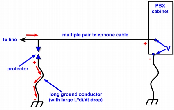
Figure 1. Lightning Protection Example
Abstract: Coupled bonding
conductors have been used for many years in the telecommunications
field for lightning protection. The principles involved are discussed,
and then examples of other uses are shown at the system and board level.
Discussion: Figure 1 shows a
classic lightning protection example. An incoming telecommunications
line, often part of a larger 50 pair cable, is connected to a lightning
protector and then continues on to a PBX (private branch exchange).
A PBX is a telephone switching system that is located on a customer
premises rather than in the telephone central office. The customer
equipment could be something as simple as a modem or answering machine,
but the use of coupled bonding conductors (to be discussed later in
this article) is usually confined to larger telephone equipment, at
least in the past.
The protector works by shunting lightning induced currents (short red arrows in Figure 1) on the telecom line to ground, hopefully protecting the telephone equipment. For the purposes of this discussion I will assume the protector is ideal, that is, the protector is a short circuit with no voltage drop across it after it fires and diverts current to the grounding conductor.
Both the protector and the PBX are grounded, but sometimes these grounding conductors, especially that of the protector, can be long. I have seen telephone lightning protector installations where the grounding conductor was 30 meters long! The inductive (Ldi/dt) voltage drop across the long grounding conductor appears as a voltage ("V" in Figure 1) across the dielectric barrier in the telephone interface circuitry. Often this barrier takes the form of a small transformer. If the Ldi/dt drop across the ground conductor of the protector has a positive polarity at the protector, then it will appear with a positive polarity at the telephone system dielectric barrier as shown in Figure 1.
If the Ldi/dt voltage drop across the long ground conductor is high enough, a few thousands of volts is possible, the dielectric barrier in the telephone system may break down. When this happens, it usually results in destroying the telephone line interface.
One way of reducing the stress on the telephone interface is to add a coupled bonding conductor. This technique was patented at AT&T Bell Labs in the early 1970's and widely used since then. Figure 2 shows the added coupled bonding conductor.
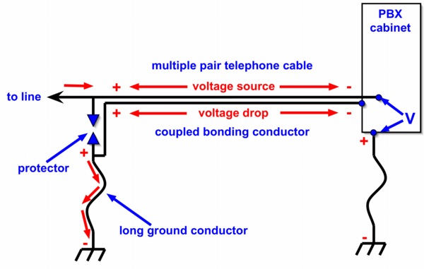
The coupled bonding conductor is connected between the ground terminal of the protector and chassis of the telephone system which has its own grounding conductor, usually connected to building steel. In the telephone world, the coupled bonding conductor is usually a 10 AWG wire that is fastened to the outside of the telephone cable along its length. Sometimes unused pairs in the cable are used instead of an external wire.
The protector works by shunting lightning induced currents (short red arrows in Figure 1) on the telecom line to ground, hopefully protecting the telephone equipment. For the purposes of this discussion I will assume the protector is ideal, that is, the protector is a short circuit with no voltage drop across it after it fires and diverts current to the grounding conductor.
Both the protector and the PBX are grounded, but sometimes these grounding conductors, especially that of the protector, can be long. I have seen telephone lightning protector installations where the grounding conductor was 30 meters long! The inductive (Ldi/dt) voltage drop across the long grounding conductor appears as a voltage ("V" in Figure 1) across the dielectric barrier in the telephone interface circuitry. Often this barrier takes the form of a small transformer. If the Ldi/dt drop across the ground conductor of the protector has a positive polarity at the protector, then it will appear with a positive polarity at the telephone system dielectric barrier as shown in Figure 1.
If the Ldi/dt voltage drop across the long ground conductor is high enough, a few thousands of volts is possible, the dielectric barrier in the telephone system may break down. When this happens, it usually results in destroying the telephone line interface.
One way of reducing the stress on the telephone interface is to add a coupled bonding conductor. This technique was patented at AT&T Bell Labs in the early 1970's and widely used since then. Figure 2 shows the added coupled bonding conductor.
Figure 2. Lightning Protection Example with Coupled Bonding Conductor Added
The coupled bonding conductor is connected between the ground terminal of the protector and chassis of the telephone system which has its own grounding conductor, usually connected to building steel. In the telephone world, the coupled bonding conductor is usually a 10 AWG wire that is fastened to the outside of the telephone cable along its length. Sometimes unused pairs in the cable are used instead of an external wire.
The addition of the coupled bonding
conductor accomplishes two things. First, the Ldi/dt drop across the
protector ground conductor will drive a current down the coupled
bonding conductor to the telephone system chassis and though its
grounding conductor to building ground. This will result in voltage
drop across the telephone equipment grounding conductor, raising the
chassis with respect to ground momentarily. Thus the voltage difference
between across the dielectric barrier in the telephone interface is
reduced. But this is small compared to the second effect.
As the lightning induced current flows on the coupled bonding conductor, it generates an Ldi/dt drop as well. If the protector polarity is positive with respect to ground, then the drop along the coupled bonding conductor will be positive to negative from the protector to the equipment chassis as indicated in Figure 2. This induces an Mdi/dt voltage source of the same polarity into the telephone conductors, where M is the mutual inductance between the coupled bonding conductor and the telephone wires. Note that as far as the dielectric barrier in the telephone system is concerned, the induced Mdi/dt source bucks the voltage to ground at the protector and lowers the stress, "V", at the dielectric barrier of the telephone system.
Let's put some numbers on this effect. Suppose the drop across the protector ground conductor reaches a peak of 3000 Volts. This is enough to break down the dielectric barrier. Let's also assume the drop across the telephone system grounding conductor is 500 Volts from the current flowing in the coupled bonding conductor over to the equipment chassis. That leaves 2500 Volts across the coupled bonding conductor. Let's also assume we can get good coupling from the coupled bonding conductor into the telephone cable. Using unused pairs in the cable as the coupled bonding conductor helps achieve this. So let's say one half of the 2500 Volt drop across the coupled bonding conductor is coupled into the telephone cable by mutual inductance. We then have a voltage source of 1250 Volts induced into telephone cable with a polarity of positive at the protector connection to negative at the dielectric barrier as shown in Figure 2.
Applying Kirchoff's voltage law (sum of voltages around a loop equals zero) around the loop (clockwise) consisting of the protector grounding conductor (starting at the gound end), the telephone cable from the protector to the dielectric barrier in the telephone system, and down the telephone system grounding conductor we get the following:
Stress at dielectric barrier (V) = 3000 Volts -1250 volts - 500 Volts = 1250 Volts!
A stress of 1250 Volts is much lower than 3000 Volts and the dielectric barrier in the telephone interface would usually survive.
I have used techniques like this to keep interference out of a cable. In one case, I grounded 46 unused pairs of a 50 pair cable about 100 meters long at both ends to make a coupled bonding conductor. The cable was in a plastic conduit immediately adjacent to a mains power cable also in a plastic conduit for most of its 100 meter length. Interference from the power cable was disrupting T1 data signals in the 50 pair cable. The use of a coupled bonding conductor composed of the 46 unused pairs was very effective and eliminated the problem, sort of a crude shield.
By the way, a shielded cable works in the same way, only better, by inducing noise from the shield into the center conductor in such a way as to cancel around the loop consisting of the source, center conductor, load, and shield.
One can imagine using this coupled bonding conductor technique on a smaller scale, for instance, on a two layer board to reduce noise coupling from one path into another.
The coupled bonding conductor and the signal conductor(s) form a parasitic transmission line that is shorted on both ends as in Figure 2. So if the line becomes something like a significant fraction of a wavelength or longer we might expect some interesting behavior due to reflections in the parasitic transmission line.
I have seen this technique work on two layer boards. On multilayer boards, the presence of the ground plane reduces and even eliminates the need to use this technique. If you do used a parallel grounded path next to a signal path over a ground plane, be sure to tie the grounded path into the ground plane at intervals that represent a very small fraction of a wavelength (say 1/20) to avoid the effects of the shorted parasitic transmission line.
A final point, power faults and other problems in the power system may cause power mains current to flow in the coupled bonding conductor under the right conditions. Putting a fuse in the conductor might be a good idea, although this is not to my knowledge done in the field and might result in destruction of the telephone line interface from induced lightning currents. I am not aware of any problems caused by mains current flowing in coupled bonding conductors.
Summary:
Coupled bonding conductors can be very effective when used for
protection of equipment or noise reduction. Be sure to take into
account any effects of the shorted parasitic transmission line
especially if used on multilayer circuit boards.
Other articles on this website related to this topic are:
- February 2002, Cable Effects Part 2: Inductive Pickup by Cables in a System
- June 2002, Using Mutual Inductance to Measure Voltage Drop in Circuits
- March 2004, Coupling Effects Between Equipment Enclosures (interactions with grounding conductors)
- April 2005, Inductive and Capacitive Coupling - Induced Current Characteristics
I have posted an audio webcast/podcast on this topic on my podcast page http://emcesd-podcast.com . The direct URL to the program is: http://emcesd-podcast.com/2007/january/2007-0110.mp3 . At this point there are about 40 programs on the site covering various topics including many of my Technical Tidbits.
If you like the information in this article and others on this website, much more information is available in my courses. Click here to see a listing of upcoming courses on design, measurement, and troubleshooting of chips, circuits, and systems.
Click here for a description of my latest seminar to be available soon titled:
EMC
Lab Techniques for Designers
(How to find EMC problems and have some confidence your system will pass EMC testing while it is still in your lab).
(How to find EMC problems and have some confidence your system will pass EMC testing while it is still in your lab).
 |
Check out my podcast containing mp3 format short tutorials, tech news and more! Just click on the microphone to see the listing
of free
audio programs. Content is added every week on technical topics so check back frequently. |
Home