
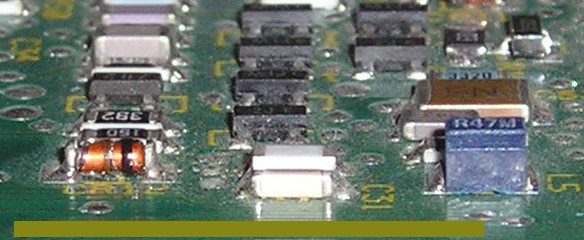
Figure 1. Circuit Board With Added Part Stacked Over Existing Capacitor
Abstract: Capacitors are
sometimes added in parallel to an existing capacitor on a printed
wiring board to improve the high frequency characteristics of the
existing capacitor for troubleshooting purposes or for a temporary fix.
Ways of mounting the added capacitor are discussed and recommendations
made. The most popular mounting method is shown to be ineffective for
some cases, especially at frequencies of hundreds of megahertz and
higher.
Discussion: Figure 1 shows a
part mounted on top of an existing capacitor. Mounting a smaller
capacitor in parallel with an existing one this way is easy to do in
the lab and therefore such added capacitors are often mounted this way.
The reason for mounting an extra capacitor in the first place is to
improve, that is lower, the impedance of the original capacitor at
frequencies of hundreds of megahertz and higher. The additional
capacitor used is smaller in value in the hope that it has lower
inductance than the larger part on the board leading to a lower
impedance of the parallel combination.
There is a problem with this approach though. Imagine removing the original capacitor on the bottom, but leaving its end caps to support the added capacitor on top. No one would stand a capacitor off the board like this on purpose! The smaller capacitor on top and its long connections to the board (the end caps of the original capacitor) would form a much larger loop above the board than the original capacitor did. The result is that the added capacitor would have much higher inductance than the original capacitor, making the added capacitor ineffective at hundreds of megahertz and higher.
Recently, I was working with a client that had mounted a small capacitor on top of a larger one just this way in an attempt to improve the RF radiated immunity of an analog circuit at 800 MHz. The added capacitor had little effect. We mounted the same additional capacitor alongside the original capacitor and a significant improvement was noted. Figure 2 shows the added part from Figure 1, moved to the side of the original one in a way similar to what we did in the lab. This is a much better way to mount an additional small capacitor in parallel with a larger one as it minimizes the effective inductance of the added capacitor. For capacitors that have one side connected to a ground plane, the performance of the added capacitor can likely be further improved if it can be connected directly to the ground plane instead of relying on the mounting pad of the original capacitor, but this takes a little luck.
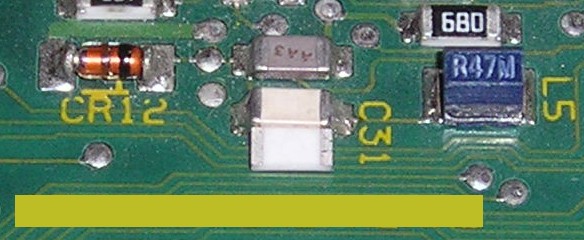
Figure 2. Circuit Board With Added Part Mounted to the Side of Existing Capacitor
There is a problem with this approach though. Imagine removing the original capacitor on the bottom, but leaving its end caps to support the added capacitor on top. No one would stand a capacitor off the board like this on purpose! The smaller capacitor on top and its long connections to the board (the end caps of the original capacitor) would form a much larger loop above the board than the original capacitor did. The result is that the added capacitor would have much higher inductance than the original capacitor, making the added capacitor ineffective at hundreds of megahertz and higher.
Recently, I was working with a client that had mounted a small capacitor on top of a larger one just this way in an attempt to improve the RF radiated immunity of an analog circuit at 800 MHz. The added capacitor had little effect. We mounted the same additional capacitor alongside the original capacitor and a significant improvement was noted. Figure 2 shows the added part from Figure 1, moved to the side of the original one in a way similar to what we did in the lab. This is a much better way to mount an additional small capacitor in parallel with a larger one as it minimizes the effective inductance of the added capacitor. For capacitors that have one side connected to a ground plane, the performance of the added capacitor can likely be further improved if it can be connected directly to the ground plane instead of relying on the mounting pad of the original capacitor, but this takes a little luck.
Figure 2. Circuit Board With Added Part Mounted to the Side of Existing Capacitor
Summary:
In general, one should try to mount an added capacitor next to, not on
top of, an existing capacitor during troubleshooting or rework of a
board. The lower inductance that results can significantly improve
circuit performance.
Additional article on this website related to this topic is:
Click here for a description of my latest seminar to be available soon titled:
EMC
Lab Techniques for Designers
(How to find EMC problems and have some confidence your system will pass EMC testing while it is still in your lab).
(How to find EMC problems and have some confidence your system will pass EMC testing while it is still in your lab).
 |
Check out my podcast containing mp3 format short tutorials, tech news and more! Just click on the microphone to see the listing
of free
audio programs. Content is added every week on technical topics so check back frequently. |
Home