
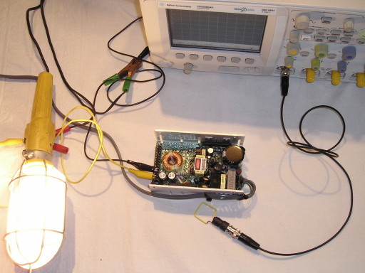
Figure 1. Test Setup for Measuring Magnetic Fields Generated by a Switching Power Supply
Abstract: Magnetic fields
emanating from switching power supplies can cause significant problems
in electronic systems. These problems are often difficult to diagnose
as
they can result in what appear to be intermittent problems or
occasional corruption of data. A simple method of measuring magnetic
fields radiating from switching power supplies is presented. The
measurement method is both easier to use and the result is more
intuitive
than conventional ways of measuring such magnetic fields.
Discussion: Figure 1 shows the
test setup with an off-the-shelf switching power supply. The work lamp contains a 12 Volt, 50 Watt lamp that acts as
a load on the power supply and the square wire loop is used to measure
the magnetic fields. The loop is the same one that appears in many of
my Technical Tidbits and is shown in Figure 2. It is made from AWG 16
gauge stiff brass wire that is first soldered to a BNC barrel adapter on one
end, then covered with heat shrink tubing, and finally the other end is pushed into the center pin receptacle of the
BNC connector. Sometimes I use this loop to inject
magnetic fields into equipment using high voltage pulses (electrical
fast transients, EFT) making the solder connection of the wire to the
BNC adapter critical for safety, but here the solder just makes the
connection of the wire to the outside of the BNC adapter more
reliable.
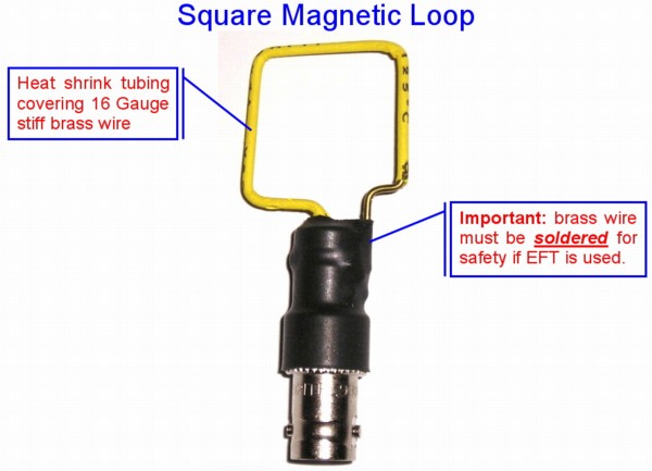
Figure 2. Wire Loop Used for Magnetic Field Measurements
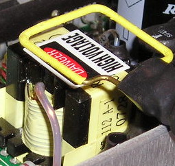
Figure 4 shows the resulting loop output into the 50 Ohm scope input impedance (50 Ohm coax was used). The resulting peak of 400 mV is large enough to affect nearby circuits and should be reduced by either changing the design of the power transformer or using a metal cover over the power supply to short out the magnetic fields emanating from the supply. Any highly conductive metal that will allow eddy currents to cancel the field from the power supply will do.
Although there may be some electric field pickup by the unshielded loop, I estimate it to be around 50 mV or less, it is not enough to change the conclusion that this power supply can be a problem if circuits are mounted directly over the top of the supply or sensitive analog circuits are within 10 cm or maybe even further away. If one were to flip the loop over and compare waveforms, the difference in the two plots would be mostly due to electric field coupling.
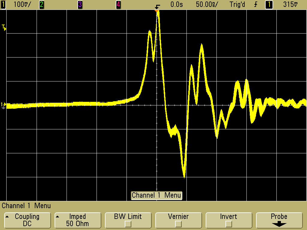
Figure 4. Scope Plot of Loop Output into 50 Ohms
(Vertical scale = 100 mV/div, Horizontal scale = 50 ns/div)
I usually like to ensure that the output from a 2.5 cm, one inch, loop loaded by 50 Ohms and passed over the surface of a switching power supply is less than 50 mV peak. At that level, problems should be rare. However, if you have sensitive circuits, even a field resulting in 50 mV in the loop can be a problem. I have seen a small computer tape backup drive that was affected by a switching supply module about 15 cm away. The switching module induced 4 Volts peak into a 2 cm loop! The tape head in such drives is a sensitive receiver for fields originating in switching supplies.
Figure 2. Wire Loop Used for Magnetic Field Measurements
Many switching power supplies do not
have a specification on allowed magnetic field emissions and this can
cause a problem. Since the radiated magnetic fields are often due to
parasitics, they can increase significantly due to a seemingly
innocuous component or layout change. The magnetic field
specifications I have seen usually specify the magnetic field itself over a
specified bandwidth. Such a specification, although technically
correct, does not lead to a quick understanding of the implications of
the field. Ultimately, the magnetic field maybe converted to a voltage
in a circuit resulting in a problem. To calculate that voltage can be a
complicated, time consuming process.
An easier way to specify the magnetic field is to define the geometry of a loop (such as the one in Figure 2), a termination for the loop (50 Ohms in this case), and the allowed induced voltage in the loop over a bandwidth. This specification has immediate intuitive value. If a two cm loop pickups up hundreds of millivolts, so will other conductors in the area. To the extend other conductors define larger loops, maybe more voltage would be induced into them. A loop output into 50 Ohms of hundreds of millivolts peak or more indicates a problematic level of magnetic emissions that can affect nearby circuits, especially circuits on two layer PCBs which are common in consumer electronics.
An easier way to specify the magnetic field is to define the geometry of a loop (such as the one in Figure 2), a termination for the loop (50 Ohms in this case), and the allowed induced voltage in the loop over a bandwidth. This specification has immediate intuitive value. If a two cm loop pickups up hundreds of millivolts, so will other conductors in the area. To the extend other conductors define larger loops, maybe more voltage would be induced into them. A loop output into 50 Ohms of hundreds of millivolts peak or more indicates a problematic level of magnetic emissions that can affect nearby circuits, especially circuits on two layer PCBs which are common in consumer electronics.
Figure 3 shows the loop of Figure 2
positioned over the power transformer of the switching power supply in
Figure 1, a likely source of magnetic field emissions. Physical layout
of the PCB in a power supply and component connections can also generate magnetic field
emissions as well.
Figure 3. Magnetic Loop Positioned Over Power Transformer of Switching Power Supply
Figure 4 shows the resulting loop output into the 50 Ohm scope input impedance (50 Ohm coax was used). The resulting peak of 400 mV is large enough to affect nearby circuits and should be reduced by either changing the design of the power transformer or using a metal cover over the power supply to short out the magnetic fields emanating from the supply. Any highly conductive metal that will allow eddy currents to cancel the field from the power supply will do.
Although there may be some electric field pickup by the unshielded loop, I estimate it to be around 50 mV or less, it is not enough to change the conclusion that this power supply can be a problem if circuits are mounted directly over the top of the supply or sensitive analog circuits are within 10 cm or maybe even further away. If one were to flip the loop over and compare waveforms, the difference in the two plots would be mostly due to electric field coupling.
Figure 4. Scope Plot of Loop Output into 50 Ohms
(Vertical scale = 100 mV/div, Horizontal scale = 50 ns/div)
I usually like to ensure that the output from a 2.5 cm, one inch, loop loaded by 50 Ohms and passed over the surface of a switching power supply is less than 50 mV peak. At that level, problems should be rare. However, if you have sensitive circuits, even a field resulting in 50 mV in the loop can be a problem. I have seen a small computer tape backup drive that was affected by a switching supply module about 15 cm away. The switching module induced 4 Volts peak into a 2 cm loop! The tape head in such drives is a sensitive receiver for fields originating in switching supplies.
Summary:
Measuring magnetic field emissions from switching power supplies by
measuring the voltage induced in a loop of specified dimensions is easy
and gives useful results.
To see a short ~five minute video in mp4 format of the measurement in Figure 1, click on the picture below. The picture links to the mp4 file on my podcast site http://emcesd-podcast.com. You can get the free multi-platform VLC media player at http://www.videolan.org if your media player cannot play mp4 files. The free player Quicktime from Apple can also play mp4 files. Clicking on the picture should play the video in your browser or you can right click and select to save the video as a file on your computer. If you can't play mp4 files, you can watch this video on YouTube using Flash by clicking here.
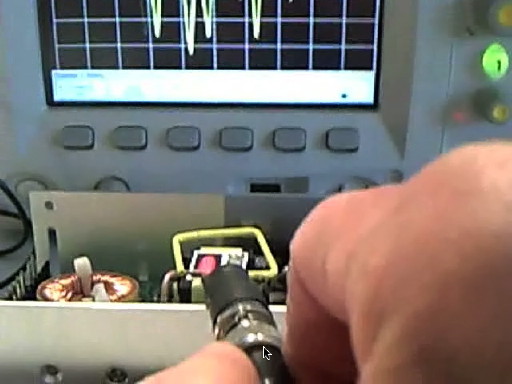
Figure 5. Click on this Picture to See Video Showing Measurement of Magnetic Field Emission from an Off-The-Shelf Switching Power Supply
(You can also watch this video on YouTube using Flash by clicking here)
To see a short ~five minute video in mp4 format of the measurement in Figure 1, click on the picture below. The picture links to the mp4 file on my podcast site http://emcesd-podcast.com. You can get the free multi-platform VLC media player at http://www.videolan.org if your media player cannot play mp4 files. The free player Quicktime from Apple can also play mp4 files. Clicking on the picture should play the video in your browser or you can right click and select to save the video as a file on your computer. If you can't play mp4 files, you can watch this video on YouTube using Flash by clicking here.
Figure 5. Click on this Picture to See Video Showing Measurement of Magnetic Field Emission from an Off-The-Shelf Switching Power Supply
(You can also watch this video on YouTube using Flash by clicking here)
Additional articles on this website related to this topic are:
- Signal and Noise Measurement Techniques Using Magnetic Field Probes (~600K)
- (1999 IEEE EMC Symposium paper)
- December 2000, An Easy to Build Shielded Magnetic Loop Probe
- February 2001, Switching Power Supplies - Effects on Circuits, Magnetic Fields
- May 2008, The Square Shielded Loop - Part 1
(Construction Details) - June 2008, The Square Shielded Loop - Part 2, Parasitic Coupling
- July 2008, The Square Shielded Loop - Part 3, Parasitic Coupling Between Unshielded Wire Loops
- August 2008, The Square Shielded Loop - Part 4, Coupling to a PCB
(From Shielded and Unshielded Magnetic Loops)
- The oscilloscope used in this Technical Tidbit is an Agilent DSO5054A, a great little scope that is easy to use and boots in 9 seconds flat!
Click here for a description of my latest seminar titled (now available online as a WebEx seminar):
EMC
Lab Techniques for Designers
(How to find EMC problems and have some confidence your system will pass EMC testing while it is still in your lab).
(How to find EMC problems and have some confidence your system will pass EMC testing while it is still in your lab).
 |
Check
out my podcast containing mp3 format short tutorials, tech news and
more! Just click on the
microphone to see the listing
of free
audio programs. Content is added every week on technical
topics so check back frequently. |
Home