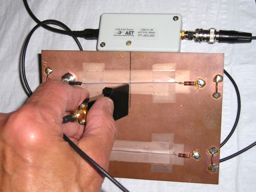
Figure 1. A Shielded Loop Being Used to Sense Signal Current from a Comb Generator
Abstract: Possible sensitivity
to electric fields/capacitive pickup has been a factor in the past in
selecting shielded magnetic loops over unshielded ones. Data is
presented to show that in the near field, shielded loops may be
required for sensing signal currents in some cases. Data presented in
prior Technical Tidbits have shown the opposite to be true for other
cases.
Discussion: Figure 1
shows a shielded magnetic loop probe held near a ground plane split to
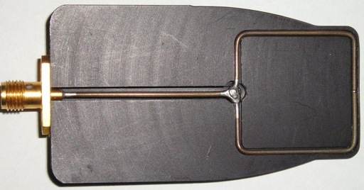
sense signal current. Probe construction is shown in the cutaway view
of Figure 2. A section of semi-rigid coax is shorted at it's end and
then bent around and the shorted end is soldered onto the coax to make
a loop. A small gap is cut in the shield to permit the loop to be
sensitive to magnetic fields. In Figure 2, the shield gap can be seen
at the midpoint of the rightmost side of the loop, opposite the
soldered junction.
Data was also taken using the unshielded wire loop shown in Figure 3 to compare the responses of the two magnetic loops and determine when the wire loop's electric field sensitivity becomes important.
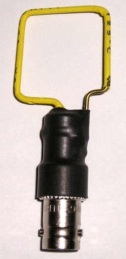
Figure 3. A Simple Wire Loop
The signal source, shown in Figure 4, for this experiment was an AET USB Powered Comb Generator. Comb generators produce a large number of harmonics that are useful in a number of frequency domain measurements normally made using a spectrum analyzer or similar instrument. But in this case, it was used to furnish fast pulses for the experiment and measurements were made on an oscilloscope. The comb generator used has a 1.8 MHz fundamental frequency and edge rates of about 400 picoseconds.
The output of the comb generator was connected to the BNC connector in the upper left corner of the circuit board in Figure 1. The resulting current in the signal path and the load resistor on the right side of the board resulted in signal current flowing around the split in the ground plane and both shielded and unshielded loops were used to sense this current.
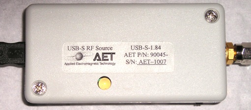
Figure 5 shows the test setup using the simple wire loop of Figure 3. This is the same setup shown in Figure 1 for the shielded loop except for the use of the unshielded loop.
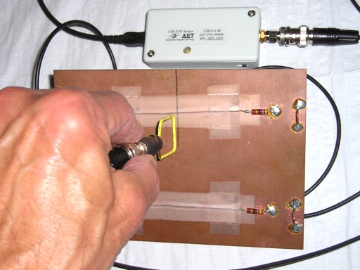
Figure 5. Test setup with unshielded wire loop
Figure 6 shows the output of the shielded loop. A resonance at about one GHz can be seen on the waveform. This could be partially due to loop self resonance or capacitive coupling to the shield. To test the effects of electric field coupling, the loop was rotated by 180 degrees. The inductive pickup should invert and any capacitive pickup should stay nearly the same. The reversed loop output is shown in Figure 7 and is just an inverted version of the wave shape in Figure 6. Since the waveforms in Figure 6 and Figure 7 are inverted with otherwise the same shape, capacitive coupling to the loop is not significant for this configuration.
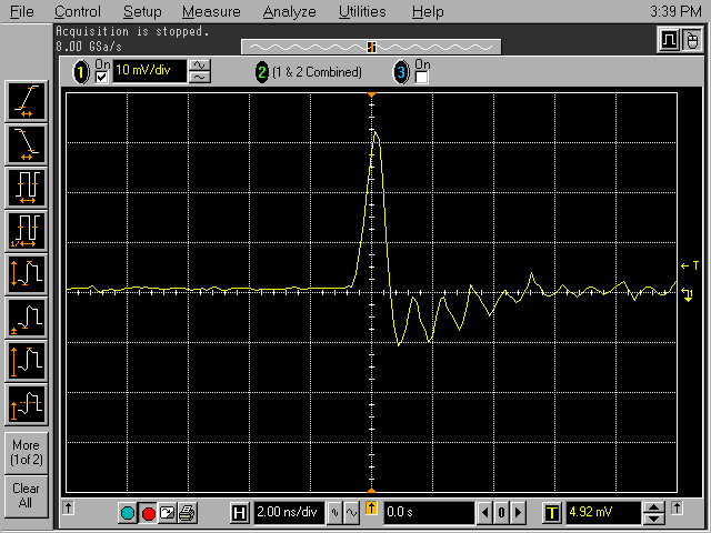
Figure 6. Output from shielded loop
(vertical scale = 10 mV/div, horizontal scale = 2 ns/div)
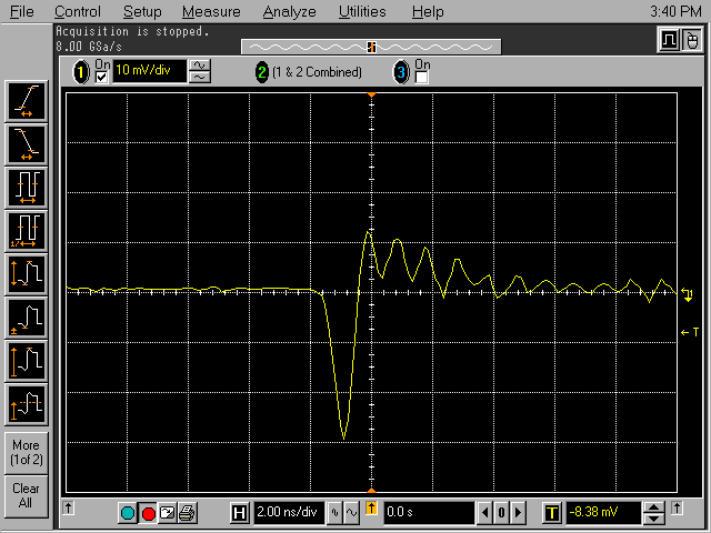
Figure 7. Output from shielded loop - reversed orientation
(vertical scale = 10 mV/div, horizontal scale = 2 ns/div)
Figures 8 and 9 show the same cases for the unshielded wire loop. One can easily see these waveforms are not just inverted versions of each other. There is significant capacitive coupling between the loop and the circuit. The capacitive coupling combined with the inductance of the wire probably produced the lower frequency resonance easily seen in Figure 9 and to a lesser extend in Figure 8.
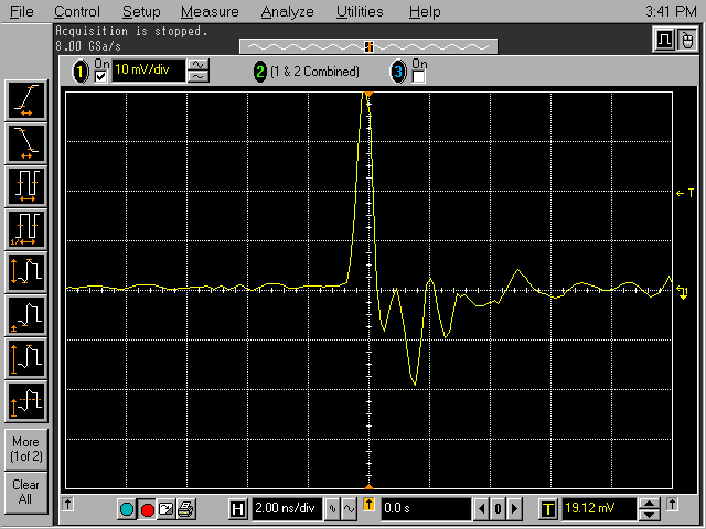
Figure 8. Output from wire loop
(vertical scale = 10 mV/div, horizontal scale = 2 ns/div)
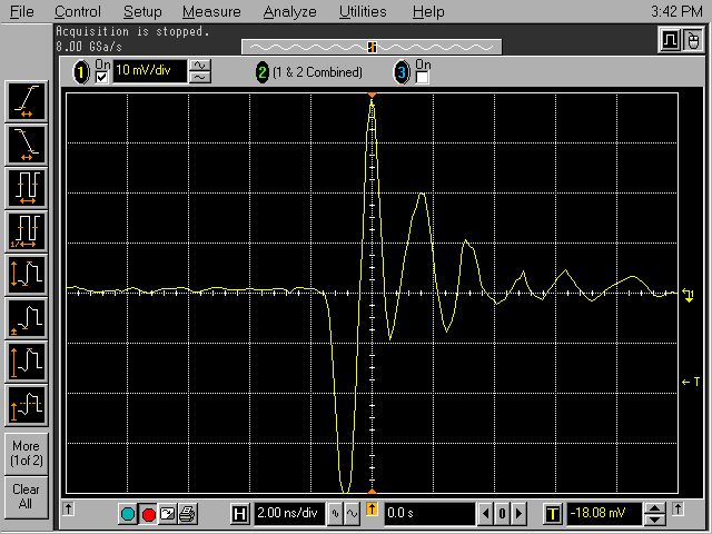
Figure 9. Output from wire loop - reversed orientation
(vertical scale = 10 mV/div, horizontal scale = 2 ns/div)
I encourage you to read the other five Technical Tidbits in the "Square Shielded Loop" series. These are linked just below the summary paragraph. In the September 2008 Technical Tidbit, "The Square Shielded Loop - Part 5," the unshielded wire loop was used for signal injection of pulses with a 2 ns edge rate. A significant capacitive effect was not present. If fact, for injecting signals into the board of Figure 1 over the ground split parallel to the signal path, the simple wire loop worked better than the shielded loop, having a flatter frequency response. In that case, the shield of the loop formed a parasitic resonant circuit with the circuit board that affected the frequency response of the coupling from the loop to the board.

Figure 2. Construction of a Square Shielded Loop
Data was also taken using the unshielded wire loop shown in Figure 3 to compare the responses of the two magnetic loops and determine when the wire loop's electric field sensitivity becomes important.

Figure 3. A Simple Wire Loop
The signal source, shown in Figure 4, for this experiment was an AET USB Powered Comb Generator. Comb generators produce a large number of harmonics that are useful in a number of frequency domain measurements normally made using a spectrum analyzer or similar instrument. But in this case, it was used to furnish fast pulses for the experiment and measurements were made on an oscilloscope. The comb generator used has a 1.8 MHz fundamental frequency and edge rates of about 400 picoseconds.
The output of the comb generator was connected to the BNC connector in the upper left corner of the circuit board in Figure 1. The resulting current in the signal path and the load resistor on the right side of the board resulted in signal current flowing around the split in the ground plane and both shielded and unshielded loops were used to sense this current.

Figure 4. AET USB Powered USB Comb Generator
Figure 5 shows the test setup using the simple wire loop of Figure 3. This is the same setup shown in Figure 1 for the shielded loop except for the use of the unshielded loop.

Figure 5. Test setup with unshielded wire loop
Figure 6 shows the output of the shielded loop. A resonance at about one GHz can be seen on the waveform. This could be partially due to loop self resonance or capacitive coupling to the shield. To test the effects of electric field coupling, the loop was rotated by 180 degrees. The inductive pickup should invert and any capacitive pickup should stay nearly the same. The reversed loop output is shown in Figure 7 and is just an inverted version of the wave shape in Figure 6. Since the waveforms in Figure 6 and Figure 7 are inverted with otherwise the same shape, capacitive coupling to the loop is not significant for this configuration.

Figure 6. Output from shielded loop
(vertical scale = 10 mV/div, horizontal scale = 2 ns/div)

Figure 7. Output from shielded loop - reversed orientation
(vertical scale = 10 mV/div, horizontal scale = 2 ns/div)
Figures 8 and 9 show the same cases for the unshielded wire loop. One can easily see these waveforms are not just inverted versions of each other. There is significant capacitive coupling between the loop and the circuit. The capacitive coupling combined with the inductance of the wire probably produced the lower frequency resonance easily seen in Figure 9 and to a lesser extend in Figure 8.

Figure 8. Output from wire loop
(vertical scale = 10 mV/div, horizontal scale = 2 ns/div)

Figure 9. Output from wire loop - reversed orientation
(vertical scale = 10 mV/div, horizontal scale = 2 ns/div)
I encourage you to read the other five Technical Tidbits in the "Square Shielded Loop" series. These are linked just below the summary paragraph. In the September 2008 Technical Tidbit, "The Square Shielded Loop - Part 5," the unshielded wire loop was used for signal injection of pulses with a 2 ns edge rate. A significant capacitive effect was not present. If fact, for injecting signals into the board of Figure 1 over the ground split parallel to the signal path, the simple wire loop worked better than the shielded loop, having a flatter frequency response. In that case, the shield of the loop formed a parasitic resonant circuit with the circuit board that affected the frequency response of the coupling from the loop to the board.
Summary:
Significant capacitive coupling was demonstrated when using an
unshielded wire loop to sense current flowing near a ground plane
split. Yet, other Technical Tidbits in the "Square Shielded Loop"
series show that for injecting a signal into a signal path crossing a
ground break, the simple wire loop was superior. Until more work is
done, one must test to see which type of loop works best for a given
situation and not just assume that one type of loop is always better.
Additional articles on this website related to this topic are:
- May 2008, The Square Shielded Loop - Part 1
(Construction details) - June 2008, The Square Shielded Loop - Part 2, Parasitic Coupling
(Electric Field Shielding of Magnetic Loops is Not Always Effective!) - July 2008, The Square Shielded Loop - Part 3, Parasitic Coupling Between Unshielded Wire Loops
- August 2008, The Square Shielded Loop - Part 4, Coupling to a PCB
(From Shielded and Unshielded Magnetic Loops) - September 2008, The Square Shielded Loop - Part 5, Measurements in the Time Domain
(From Shielded and Unshielded Magnetic Loops) - December 2000, An Easy to Build Shielded Magnetic Loop Probe
-
Signal and Noise Measurement Techniques Using
Magnetic Field Probes (~600K)
(1999 IEEE EMC Symposium paper)
If you like the information in this article and others on this website, much more information is available in my courses. Click here to see a listing of upcoming courses on design, measurement, and troubleshooting of chips, circuits, and systems. Click here to see upcoming seminars in Newport Beach, CA.
Click here for a description of my latest seminar titled (now also available online as a WebEx seminar):
EMC
Lab Techniques for Designers
(How to find EMC problems and have some confidence your system will pass EMC testing while it is still in your lab).
(How to find EMC problems and have some confidence your system will pass EMC testing while it is still in your lab).
 |
My new website for engineers and technicians, CircuitAdvisor.com, is coming! The site will contain technews and analysis programs, cartoons, multimedia tutorials and more.The site will be open soon. |
Home
