Abstract: Radiated emissions
from electronic equipment can be a strong function of how the equipment
is operated. In the case of class D audio amplifiers, the audio signal
driving the amplifier can have a large effect on emissions. Test
results and implications are discussed as they relate to the philosophy
of radiated emissions testing.
Class D (and newer
class "Z") digital audio amplifiers are potentially a source of noise
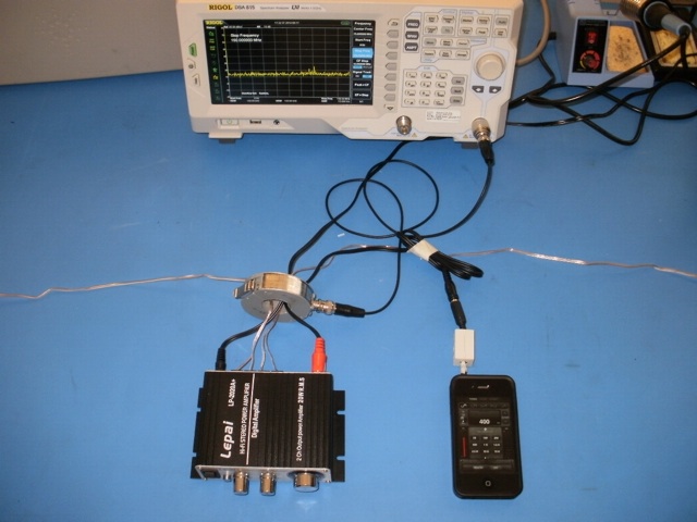
strong enough to exceed international radiated emissions limits. Figure
1 shows the test setup for a Lepai LP-2020A+ digital class Z
stereo amplifier. Two 8 Ohm power resistors serve as speaker loads and
are connected at the ends of the small wires exiting to the right and
left. A Fischer F-33-1 current probe is placed over the power,
speaker leads, and audio input leads from the amplifier. The amplifier is sitting on a blue
ESD mat covering the table. The
June 2014 Technical Tidbit
showed that this amplifier couples to the blue conductive mat as a
reference to drive common mode current out any leads connected to the
amplifier. In this article, I will show that the common mode current is
a strong function of the audio signal source content and has
implications for how equipment is tested for radiated emissions.
Figure 1 shows the test setup including an iPhone running the app
"Tone Gen Pro." The app can output a number of waveforms at audio
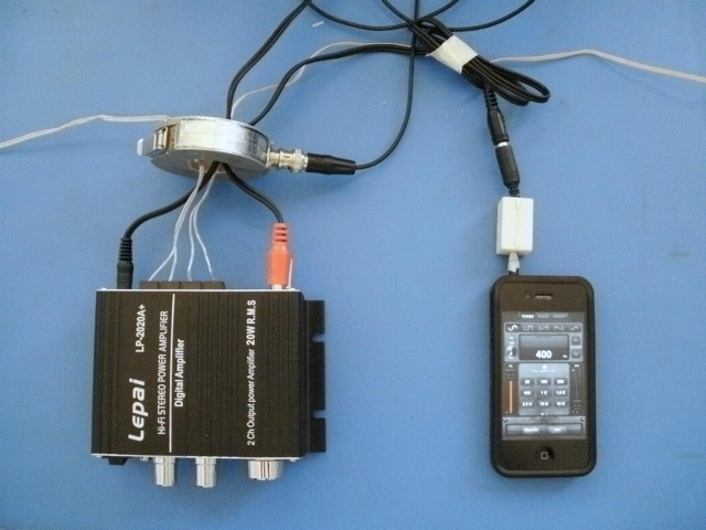
frequencies and amplitudes. Figure 2 shows a close-up of the test setup.
Figure 2. Close-up of Test Setup for Measuring Common Mode Current on the Amplifier Cables
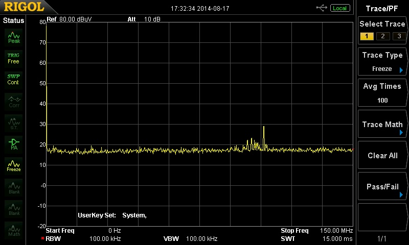
Figure 3 shows the common mode current for the amplifier turned
off, but with the iPhone on to make sure the iPhone was not
contributing to the displayed common mode current being investigated.
The small peaks shown correspond to signals in the FM broadcast band
and are not due to the iPhone.
Figure 3. Common Mode Current -Amplifier Off
(15 MHz/div from 0 to 150 MHz, Max Hold mode)
The amplifier was then turned on, but idling with no audio input. The
resulting common mode current is shown in Figure 4. Given the
sensitivity of the F-33-1 current probe, the common mode current that
would begin to cause a possible Class B (residential) emissions problem
is a horizontal line at 30 dBuV (left scale). At about 55-60 Mhz and at
about 90-100 MHz, the common mode current reaches about 33 dBuV,
potentially signaling enough common mode current to cause an emissions
problem at those frequencies.
The amplifier is likely producing broadband noise throughout the
frequency spectrum displayed (0 to 150 MHz), but cable resonances cause
common mode current to peak at those frequencies shown in the display.

Figure 4. Common Mode Current - Amplifier On, Idle State, No Audio Signal
(15 MHz/div from 0 to 150 MHz, Max Hold mode)
Figure 5 shows the iPhone Tone Gen
Pro app set to produce a 400 Hz sinewave. The amplitude was set so that
the amplifier was working hard but not overdriven to saturation.
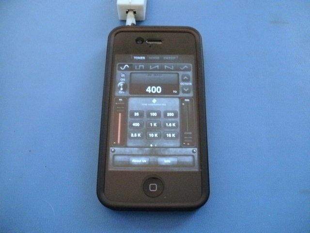
Figure 5. 400 Hz Continuous Tone Supplied from iPhone App
Figure 6 shows the resulting common mode current. Now the common mode
current peaks up at about 44 dBuV, enough to potentially cause a Class
A (industrial) emissions failure at about 50 MHz. Since this amplifier
is a Class B device, it is very likely to show a Class B failure in a
radiated emissions test performed at an official EMC test lab.
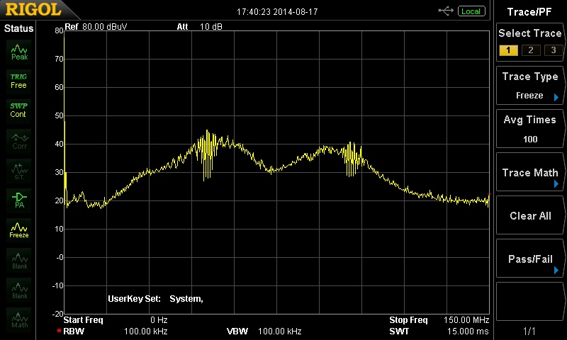 Figure 6.
 Common Mode Current - Amplifier On, 400 Hz Tone Supplied from iPhone App
(15 MHz/div from 0 to 150 MHz, Max Hold mode)
Figure 7 shows the iPhone set to
output a popular rock song from the 80s (The Breakup Song by the Greg
Kihn band) which has a high average power level as well as high peaks.
Figure 8 shows the resuting common mode current. All the spectrum
analyzer plots, including Figure 8, were made in the "Max Hold" mode.
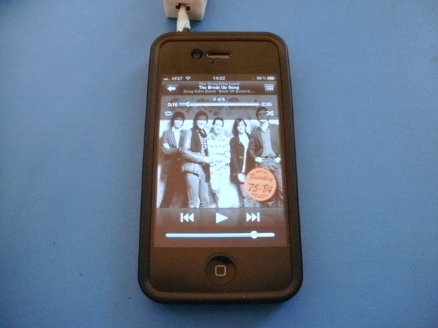 Figure 7.
 Music Supplied from iPhone App
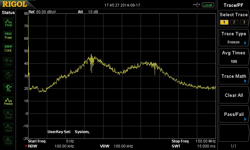 Figure 8.
 Common Mode Current - Amplifier On, Music Supplied from iPhone App
(15 MHz/div from 0 to 150 MHz, Max Hold mode)
The common mode current peaks at about 47 dBuV, a likely Class A
and definite Class B radiated emissions failure. Quasi-peak weighting
may help here somewhat, but the common mode current would not likely
fall below the 400 Hz sine wave level in Figure 6.
This brings up a philosophical question for radiated emissions testing
(and a lot of other testing as well). If I were at a test lab trying to
get my design tested for radiated emissions, and this amplifier was my
product, what audio signal should I use? A quiet classical piece, hard
rock, a sine wave, a square wave, or something else. And should the
level be at max volume without saturating the amplifier? From the
data above, the choice of audio source could make the difference
between passing and failing.
The same would likely hold true for a digital device. What bit patterns
should be used? I have seed the radiated emissions status (pass or
fail) depend on the bit patterns used in data that was being moved
around.
In both cases, should worst case be used even if it is very unlikely
(400 Hz tone for instance in an amplifier) or should typical sources
(music at a reasonable volume setting) be used? Human voice has a very
high peak to average ratio so the amplifier would be more likely to
pass using it, especially if Quasi-Peak averaging were used (as allowed
in radiated emissions testing). What should be done?
Summary: Class D
amplifiers can make good noise sources for experiments. In this case,
the choice of audio source and its amplitude had a significant effect
on common mode current on leads from the amplifier and therefore on
radiated emissions. The philosophical question is: what conditions
should I use in emissions testing of any device? Worst case conditions
or likely conditions?
Technical Tidbits on this site related to this article:
Equipment used in this Technical Tidbit: