Common Mode Conducted Noise on Outputs
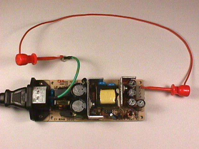
Figure 1. Switching Power Supply With Input/Output Grounds Connected

Address: P. O. Box 1457, Los Gatos,
CA 95031
TEL:
800-323-3956/408-356-4186
FAX:
408-358-3799
Mobile: 408-858-4528
URL:
www.dsmith.org
Email: doug@dsmith.org
Figure 1. Switching Power Supply With Input/Output Grounds Connected
This Technical Tidbit is the second in a series of articles on switching power supply induced system problems. The first article covered magnetic field emission from switching power supplies.
Solving intermittent problems that occur in equipment can use significant engineering resources. An important source of intermittent system problems is common mode noise current that is rarely covered by power supply specifications or EMC tests, yet represent a major source of system problems. It can take quite a while for a series of 50 kHz spikes to line up with a vulnerable state in a system making for an apparent intermittent problem. The cause of a problem due to switching power supply noise is often difficult to find because of its hidden, unlikely nature.
Switching power supplies are capable of generating noise in several modes. A couple of these modes can disrupt system operation by signal corruption in circuits which are not even being powered from the supply in question. This Technical Tidbit covers one of these modes, common mode noise currents flowing between DC isolated outputs or between an isolated output and the power supply input ground. These currents can reach substantial amplitudes and cause Ldi/dt voltage drops along a conductor connecting the input and output returns of more than one Volt/cm!
Often, when power supplies are tested they are connected to a load, but the input ground (power source ground) and output ground (typically signal ground) are not connected for the test. However, in many electronic systems these grounds are connected, sometimes at a single point, sometimes at multiple points.
The noise currents flowing from isolated output to isolated output or input grounds are due to parasitic coupling in the power supply and can vary substantially between units. Even a small seemingly innocuous design change can cause a 10X increase of these noise currents. Figure 2 shows one way to measure the Ldi/dt drop due to the noise current.
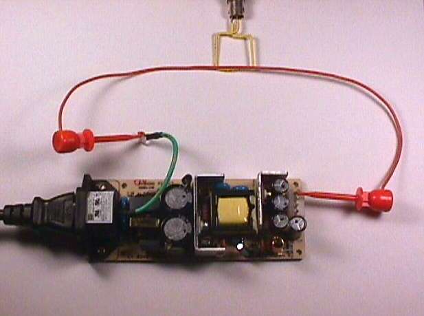
Figure 2. Measuring Common Noise Ground Currents Produced by a Switching
Supply Using a Magnetic Loop.
The input and output grounds are connected on the test bench with a wire. The Ldi/dt voltage drop in the wire can be estimated by mutual induction from a square magnetic loop made from a piece of stiff wire. The output of the loop will be Mdi/dt and represent a lower bound the voltage drop along the wire. Be sure to load the scope end of the coaxial cable from the loop in the cable characteristic impedance, usually 50 Ohms. The power supply load should be varied over its rated output current range. Some power supplies are noisy at low load currents and others at higher load currents.
Another, more direct, way to measure the voltage drop caused by these noise currents is shown in Figure 3. In this case, the voltage drop across the conductor is measured directly using a balanced probe, such as a balanced coaxial probe (link to information on this probe is at the end of the article). Again, be sure to vary the load current of the power supply. There are a number of other ways to characterize common mode noise currents, but the ones shown here are easy and sufficient in most cases.
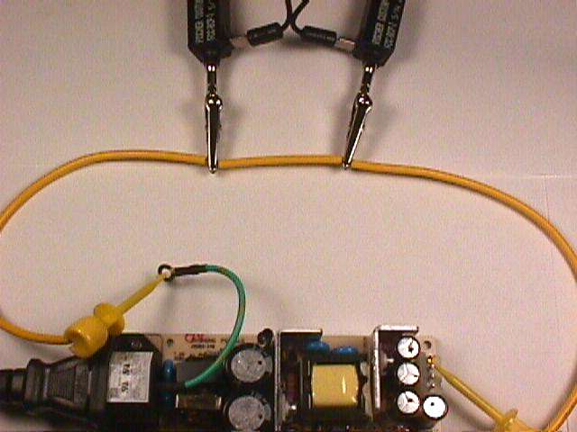
Figure 3. Measuring Common Noise Ground Currents Produced by a Switching
Supply Using A Balanced Probe.
How about acceptable limits? Certainly 1 volt induced across 1 cm of wire is too high. Sooner or later a problem due to the noise current will surface. Often, this occurs when an otherwise innocuous change is made in a nearby circuit and then the system no longer works. A limit of 50 mV/cm will suffice for many circuits. Systems with optical to electrical signal conversion and others with small analog signals may require even lower limits.
For information on the Balanced Coaxial Probe, try the link below from this website: