Differential Measurement of Cable EMI Currents
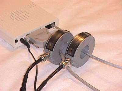
Figure 1. Measurement of Cable Currents Due to EMI
(modem phone line and serial cable)

Address: P. O. Box 1457, Los Gatos,
CA 95031
TEL:
800-323-3956/408-356-4186
FAX:
408-358-3799
Mobile: 408-858-4528
URL:
www.dsmith.org
Email: doug@dsmith.org
Figure 1. Measurement of Cable Currents Due to EMI
(modem phone line and serial cable)
Immunity problems in electronic equipment caused by conducted EMI (electromagnetic interference) noise on cables can be difficult to diagnose, especially if the resulting operational problems appear to be intermittent in nature. Sources of such noise include electrical fast transients (EFT), electrostatic discharge (ESD), and radio transmitters. A simple procedure using a matched set of current probes can be used to troubleshoot such immunity problems in equipment. By determining the path of the resulting noise currents in the equipment, one has gone a long way to finding the mechanism of the problem in many cases.
The procedure uses a pair of matched current probes to find which equipment cables are carrying the EMI current, and the direction of the current flowing on each cable. In Figure 1 above, high frequency energy from an ESD event is coupled onto the telephone cable (upper right cable). The resulting EMI current is monitored by a current probe. A pair of matched Fischer F-33-1 current probes are used for this example. The question is, for this case, which of the other two cables are carrying the EMI current out of the equipment. Current arriving on one cable must exit on the other cables or radiate from the equipment itself.
A second current probe is placed on the other cables one at at time
to determine the role of those cables in creating a path for the EMI current
in the equipment. Figure 2 shows the result of the second probe being placed
on the serial cable as shown in Figure 1. The blue trace is the phone cable
and the yellow trace is the serial cable. The current probes are placed
on the two cables in the same orientation with respect to the equipment
so we would expect current entering on the phone cable to produce the opposite
polarity on the trace as current exiting on the serial cable, This is just
what happens in Figure 2. The first peak of current on the phone cable
is -800 mA. The serial cable is carrying a little less than half of that
current, about +300 mA away from the equipment. There is a slight time
delay of about 1 ns between the two currents that represents the time for
the current to enter the equipment and then exit on the other cable. The
small amount of noise to the left of the current peaks is due to radiation
directly through the air from the ESD source as opposed EMI currents being
conducted on the cables.
Figure 2. ESD Currents on Modem Cables
(phone line and serial cables)
Figure 3 shows the second current probe moved from the serial cable
to the power cable. The result is shown in Figure 4.
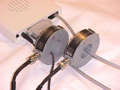
Figure 3. Measurement of Cable Currents Due to ESD
(modem phone line and power cable)
Figure 4 shows that the power cable only conducts a little over +150
mA away from the equipment. Twice as much current is being conducted on
the serial cable as on the power cable. That information would allow a
designer to pay attention to the circuitry around the phone and serial
cables. Hopefully, there is no critical circuitry between the connectors
for these cables on the circuit board.
Figure 4. ESD Currents on Modem Cables
(phone line and power cable)
Often, the cable or cables carrying noise into the equipment are not even known. In that case, the pair of current probes can be used to find the relative direction and magnitude of cables carrying currents into or out of the system. Usually, the offending current is primarily coming in on one cable and exiting on one or more of the other cables.
This example also points out a useful design rule. To minimize the effect of external conducted noise on equipment, keep connectors as physically close to each other as system design permits. Doing so will minimize the chances that EMI current entering on one cable and exiting on others will pass though critical circuitry on the way.
Other articles containing information on current probes on this site include:
The above waveforms were taken with an Agilent
Infinium 54845a oscilloscope.
More detailed information about this and other topics on this website is available from this site's new subscription service (to start this Fall) and seminars.