
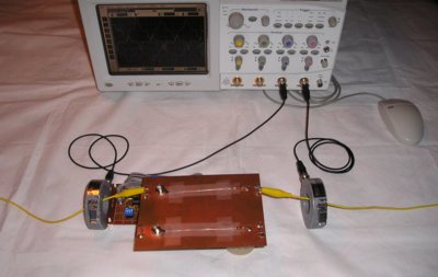
Figure 1. Test Setup for Measuring Common Mode Currents Due to a Ground Plane Break
Abstract: Signals that cross ground/power
plane breaks on printed wiring boards (PWBs) can cause common mode
currents on system cables resulting in excessive EMI emissions
in addition to any signal quality issues. Data is presented
that shows significant emissions can result from a small 5 cm plane
break, even at frequencies of only tens of megahertz.
Discussion: Signals crossing ground/power plane breaks can cause all sorts of problems including radiated EMI, lack of immunity to EMI, crosstalk, and degradation of the signal risetime. These effects are due mostly to the loop formed by the signal's returning current having to find its way around the plane break. The effect on emissions due to common mode currents on system cables resulting from a signal to crossing a plane break is addressed in this article. The data is applicable to PWBs where a break is cut through all ground and power planes.
Figure 1 shows the test setup used to generate the data. A small oscillator operating at about 30 MHz with signal edge rates of about two nanoseconds is coupled to the test board through a short BNC coupler. The signal amplitude is about three volts peak to peak into the ~50 Ohm load on the board. A close-up of the board, generator, and current probes is shown in Figure 2. Two meter yellow wires are attached to the ground plane at both sides of the board. A pair of matched Fischer F-33-1 current probes are used to measure the resulting common mode current in these wires.
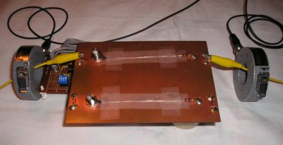
Figure 2. Detail of Test Setup
Figure 3 shows the test board in greater detail. The plane break is about five cm in length and cuts through the copper planes on both sides of the board. The planes are shorted together by the BNC connectors.
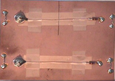
Figure 3. Test Board
The common mode current on the yellow two meter wires where the signal passed over the five cm plane break is shown in Figure 5. Keep in mind that the signal frequency is only about 30 MHz. Note that the output of the probes are in phase. This means that the current is flowing along one wire and onto the other wire, pushed by the voltage difference between them on the ground plane. The wires are acting like a dipole antenna.
The peak current is about one milliampere. If we estimate the RMS value to be about 500 microamperes and about half of that is at the fundamental frequency, then there is about 250 microamperes of current flowing at about 30 MHz. This level of current would result in emissions that are about 34 dB over EN55022 or FCC emissions specifications for class B consumer equipment (About five microamps of current fed into a one half wavelength dipole radiates near the allowed level of emissions for class B equipment.). Normally one needs the dynamic range of a spectrum analyzer to see currents in this range. However, even at 30 MHz, the common mode currents generated by a three volt square wave with two nanosecond edges crossing a five cm plane break are large enough to be easily seen on an oscilloscope. And this at only 30 MHz! Imagine the results at 300 MHz or for longer plane breaks than the 5 cm used here.
The reason for the increased common mode current for the path that crosses the plane break is that the signal's return path in the ground plane is forced to go around the edge of the break as shown in my January, 2003 Technical Tidbit. One way to think about this for small plane breaks is that the break opens up a loop between the signal and its return path in the ground plane. A voltage results across the the inductance of the loop in the ground plane caused by the signal current. The voltage across the ground plane then drives a common mode current on system cables.
Summary: Yet another problem caused by routing signals over plane breaks is described, common mode currents on system cables. For the relatively benign 30 MHz example used, emissions specifications appear to be exceeded by about 34 dB for class B (consumer) equipment.
Discussion: Signals crossing ground/power plane breaks can cause all sorts of problems including radiated EMI, lack of immunity to EMI, crosstalk, and degradation of the signal risetime. These effects are due mostly to the loop formed by the signal's returning current having to find its way around the plane break. The effect on emissions due to common mode currents on system cables resulting from a signal to crossing a plane break is addressed in this article. The data is applicable to PWBs where a break is cut through all ground and power planes.
Figure 1 shows the test setup used to generate the data. A small oscillator operating at about 30 MHz with signal edge rates of about two nanoseconds is coupled to the test board through a short BNC coupler. The signal amplitude is about three volts peak to peak into the ~50 Ohm load on the board. A close-up of the board, generator, and current probes is shown in Figure 2. Two meter yellow wires are attached to the ground plane at both sides of the board. A pair of matched Fischer F-33-1 current probes are used to measure the resulting common mode current in these wires.
Figure 2. Detail of Test Setup
Figure 3 shows the test board in greater detail. The plane break is about five cm in length and cuts through the copper planes on both sides of the board. The planes are shorted together by the BNC connectors.
Figure 3. Test Board
The resulting common mode current where the signal is applied to the path over solid ground is shown
in Figure 4. The oscillator frequency was tuned to attempt to excite
the resonance of the two meter wires, but no significant current
resulted as shown in Figure 4 using a scale of one half milliampere per division.
Figure 4. Common Mode Current For Solid Ground Plane Case
The common mode current on the yellow two meter wires where the signal passed over the five cm plane break is shown in Figure 5. Keep in mind that the signal frequency is only about 30 MHz. Note that the output of the probes are in phase. This means that the current is flowing along one wire and onto the other wire, pushed by the voltage difference between them on the ground plane. The wires are acting like a dipole antenna.
The peak current is about one milliampere. If we estimate the RMS value to be about 500 microamperes and about half of that is at the fundamental frequency, then there is about 250 microamperes of current flowing at about 30 MHz. This level of current would result in emissions that are about 34 dB over EN55022 or FCC emissions specifications for class B consumer equipment (About five microamps of current fed into a one half wavelength dipole radiates near the allowed level of emissions for class B equipment.). Normally one needs the dynamic range of a spectrum analyzer to see currents in this range. However, even at 30 MHz, the common mode currents generated by a three volt square wave with two nanosecond edges crossing a five cm plane break are large enough to be easily seen on an oscilloscope. And this at only 30 MHz! Imagine the results at 300 MHz or for longer plane breaks than the 5 cm used here.
The reason for the increased common mode current for the path that crosses the plane break is that the signal's return path in the ground plane is forced to go around the edge of the break as shown in my January, 2003 Technical Tidbit. One way to think about this for small plane breaks is that the break opens up a loop between the signal and its return path in the ground plane. A voltage results across the the inductance of the loop in the ground plane caused by the signal current. The voltage across the ground plane then drives a common mode current on system cables.
Figure 5. Common Mode Current For Split Ground Plane Case
Summary: Yet another problem caused by routing signals over plane breaks is described, common mode currents on system cables. For the relatively benign 30 MHz example used, emissions specifications appear to be exceeded by about 34 dB for class B (consumer) equipment.
Other articles on this website related to this topic are:
- December 2002, Crossing Ground Plane Breaks, A Source of Crosstalk
- January 2003, Crossing Ground Plane Breaks - Part 2, Tracing Current Paths
- February 2003, Crossing Ground Plane Breaks - Part 3, Immunity to Radiated EMI
- January 2005, Crossing Ground Plane Breaks - Part 4, Risetime Effects on Signals
- 50 MHz Oscillator construction plans (~260K)
Additional Material: An in-depth audio-visual format tutorial on this subject, covering background as well as more technical details, is available at: http://emcesd-p.com.
If you like the information in this article and others on this website, much more information is available in my courses. Click here to see a listing of upcoming courses on design, measurement, and troubleshooting of chips, circuits, and systems.
Equipment used in this article includes:
Top of page
Home