
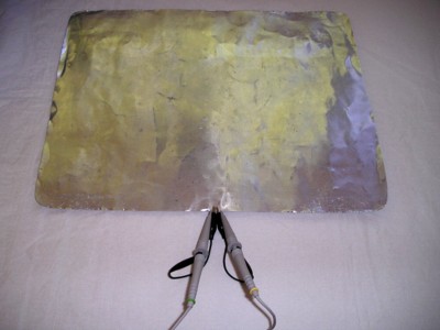
Figure 1. Two Passive Probes Connect to Metal Plane
Abstract: A popular
engineering troubleshooting technique is to measure power to ground
noise on a board or in a system, often with a differential measurement using two unbalanced
probes and channel subtraction in the scope. Such
measurements at today's speeds are generally unreliable. Data is
presented to illustrate limitations of this type of measurement.
Discussion: Figure 1 shows two
unbalanced probes shorted by their ground leads and connected to a
metal plane. The metal plane simulates the ground plane of a multilayer
printed wiring board. I call shorting the probes like this a
"null" experiment since the result should be zero. To the extent it is not
zero, the result is the inherent error or noise level of the measurement
setup. It makes no sense to try and measure signals smaller than the
result of the null experiment. Figure 2 shows a close-up of the probe
connections. The probe cables were allowed to assume random positions
on the table between the metal plane and the oscilloscope.
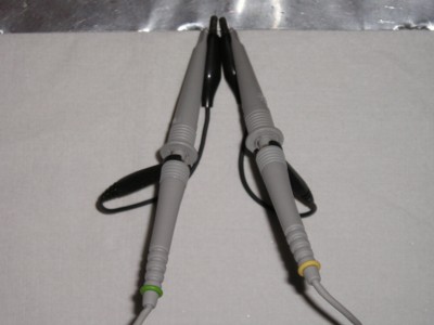
Figure 2. Close-up of Probes From Figure 1
To simulate environmental noise, an
ESD simulator was discharged to its own ground lead about 1 1/2 meters
from the probes and plate shown in Figure 1. The result is shown
in Figure 3. Note that the peak value recorded on both channels was
greater than the 4 Volt limit on the scope screen. Perhaps more
important that the absolute magnitude of the signals recorded in Figure
3 is the fact that the two probes are ringing at different frequencies
due to the probe cables being separated on the table and taking
different paths to the scope. Taking the difference in the scope of the
two channels shown in Figure 3 would not make much sense. In fact, as
the top trace touches - 4 Volts, the bottom trace is just touching +4
Volts. The difference would be at least 8 volts! This is larger than either signal by itself.
Figure 3. Scope Plot of Probe Outputs with Nearby ESD
The probe cables were then
twisted together, about one twist per six inches along the cables.
Figure 4 shows the resulting waveforms. The two channels are at
least ringing at the same frequencies now and look similar. Maybe a
subtraction of the two traces makes sense to reduce the common mode
interference from the ESD event.
Figure 4. Scope Plot of Probe Outputs with Nearby ESD With Probe Cables Twisted
Upon closer inspection of Figure 4
though, significant differences are present. Look at the two traces
around one division from the left side of the screen, at the first
positive peak of the waveforms. The common mode rejection achieved by
subtracting the two channels in the scope is compromised and will still yield an apparent
differential voltage that is significant in that region of the scope
traces. In general, one is lucky to achieve 10 dB of common mode
rejection using separate probes and channel subtraction in the scope
above a few tens of megahertz.
A better method is needed. One could try to float the ground leads and connect them together, but that will increase the apparent common mode signal requiring more attenuation of the common mode signal. Also the large loop composed of the ground leads and probe tips will pick up significant noise.
A better method is needed. One could try to float the ground leads and connect them together, but that will increase the apparent common mode signal requiring more attenuation of the common mode signal. Also the large loop composed of the ground leads and probe tips will pick up significant noise.
The December 2006 Technical Tidbit
will propose a solution to the problem of making differential
measurements in the presence of significant interference.
Summary:
The use of two separate probes coupled with channel subtraction
generally does not work well for differential measurements above a few
tens of megahertz in the presence of significant interference. Null
experiments should always be done to prove the results of a measurement
around strong interference such as ESD. The null experiment results
presented show the limitations of using two separate probes to make
differential measurements.
Other articles on this website related to this topic are:
- July 1999: The Shorted Scope Probe Problem
- June 2000 supplement, Ground Lead, Friend or Foe?
- September 2001, Improving FET Probe Immunity to Unwanted Noise Pickup
- March 2003, Minimizing Errors in Oscilloscope Measurements
Click here for a description of my latest seminar to be available in the Fall titled:
EMC
Lab Techniques for Designers
(How to find EMC problems and have some confidence your system will pass EMC testing while it is still in your lab).
(How to find EMC problems and have some confidence your system will pass EMC testing while it is still in your lab).
 |
Check out my podcast containing mp3 format short tutorials, tech news and more! Just click on the microphone to see the listing
of free
audio programs. Content is added every week on technical topics so check back frequently. |
Home