
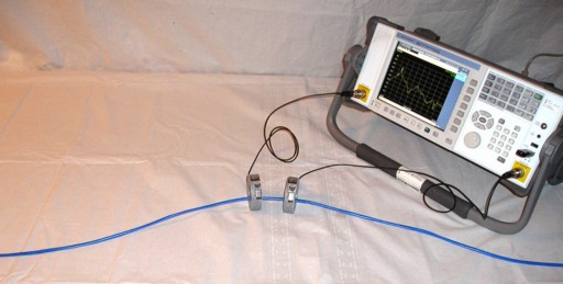
Figure 1. Cable Resonance Test Setup Using a Pair of Matched F-33-1 Current Probes
Abstract: A technique for
using current probes to measure cable resonances is described. A
swept frequency voltage is induced on a cable by one current probe
and the resulting current measured using a second one. This technique
can be especially useful
in troubleshooting EMC emissions problems as well as other noise
related problems
in equipment designs.
Discussion:
This Technical Tidbit could be considered an extension of my
1998 IEEE EMC Symposium paper "Current Probes, More Useful
Than You Think."
In that paper, current measurements were made in the frequency and time
domain. In this Technical Tidbit, I am turning one current probe around
and using it to inductively couple a swept frequency voltage into wires
and cables and then measuring the resulting current with a second
probe.
Figure 1 shows the experimental setup using a pair of matched Fischer Custom Communications F-33-1 current probes installed at the middle of a two meter Cat5 network cable and an Agilent N1996A Spectrum Analyzer. The N1996A has the ability to make several network analyzer like measurements, in this case a two port insertion loss measurement was used. One could also use a standard spectrum analyzer with a tracking generator.
The F-33-1 probe on the left is being fed from the swept frequency tracking generator in the N1996A. Many current probes, including the F-33-1 probes in Figure 1, can be thought of as transformers and as such the probe on the left couples a series voltage onto the cable. The second probe on the right is connected to the receiver input of the N1996A and is used to measure the current on the cable.
The injected signal voltage from the F-33-1 probe on the left will drive a current along the cable. At the frequencies where the driving point impedance is low, more current will flow. In Figure 1, the middle of the cable has a relatively low driving point impedance when the cable is 1/2 wavelength long at a frequency. At that frequency, the cable is just a center fed one half wavelength dipole with a driving point impedance near 70 Ohms. As the frequency of the signal is moved from this value, either higher or lower, the driving point impedance increases dramatically resulting in lower current. This is shown in Figure 2.
Figure 2 shows a plot of the right hand F-33-1 probe's output. Notice the sharp peak in current at about 54.7 MHz. This is about the frequency one would expect to see a current peak. At 54.7 MHz, one half wavelength in free space is about 2.74 meters. Given the speed of propagation on the cable is likely 75% or so of the free space value, that gives two meters as about one half wavelength at 54.7 MHz. The frequency of the peak current is also modified somewhat by the metal frame under the wooden tabletop as well.
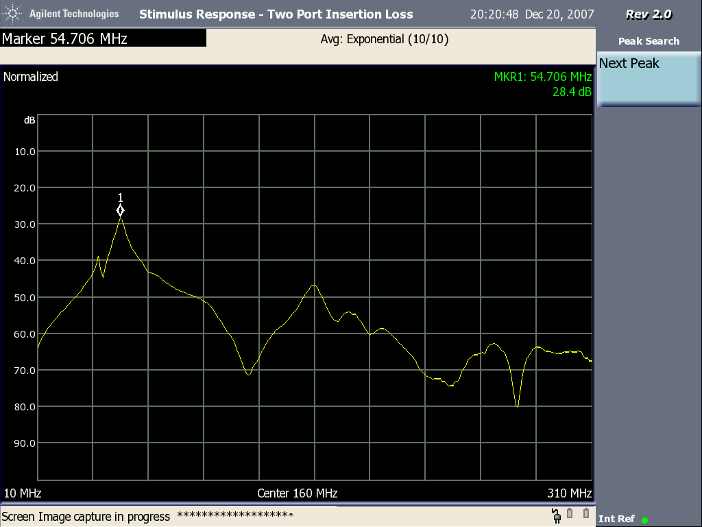
Figure 2. Cable Current vs. Frequency Showing Primary Resonance at 54.7 MHz
There is another less important resonance at about 160 MHz (center of plot) and a few low current valleys as well. Note the low current valley just to the right of the 54.7 MHz peak at about 120-125 MHz. That valley occurs at the frequency where the cable is electrically about one wavelength long including the effect of the table's metal frame. At that frequency, the driving point impedance of the cable is very high resulting in the dip in current. The current there is about 40 dB lower, 1/100th, than the current peak at 54.7 MHz.
By the way........one of the corollaries to Murphy's law states that your main system cable will resonate (low impedance driving point) at the third harmonic of your system clock. Better check it!
Figure 1 shows the experimental setup using a pair of matched Fischer Custom Communications F-33-1 current probes installed at the middle of a two meter Cat5 network cable and an Agilent N1996A Spectrum Analyzer. The N1996A has the ability to make several network analyzer like measurements, in this case a two port insertion loss measurement was used. One could also use a standard spectrum analyzer with a tracking generator.
The F-33-1 probe on the left is being fed from the swept frequency tracking generator in the N1996A. Many current probes, including the F-33-1 probes in Figure 1, can be thought of as transformers and as such the probe on the left couples a series voltage onto the cable. The second probe on the right is connected to the receiver input of the N1996A and is used to measure the current on the cable.
The injected signal voltage from the F-33-1 probe on the left will drive a current along the cable. At the frequencies where the driving point impedance is low, more current will flow. In Figure 1, the middle of the cable has a relatively low driving point impedance when the cable is 1/2 wavelength long at a frequency. At that frequency, the cable is just a center fed one half wavelength dipole with a driving point impedance near 70 Ohms. As the frequency of the signal is moved from this value, either higher or lower, the driving point impedance increases dramatically resulting in lower current. This is shown in Figure 2.
Figure 2 shows a plot of the right hand F-33-1 probe's output. Notice the sharp peak in current at about 54.7 MHz. This is about the frequency one would expect to see a current peak. At 54.7 MHz, one half wavelength in free space is about 2.74 meters. Given the speed of propagation on the cable is likely 75% or so of the free space value, that gives two meters as about one half wavelength at 54.7 MHz. The frequency of the peak current is also modified somewhat by the metal frame under the wooden tabletop as well.
Figure 2. Cable Current vs. Frequency Showing Primary Resonance at 54.7 MHz
There is another less important resonance at about 160 MHz (center of plot) and a few low current valleys as well. Note the low current valley just to the right of the 54.7 MHz peak at about 120-125 MHz. That valley occurs at the frequency where the cable is electrically about one wavelength long including the effect of the table's metal frame. At that frequency, the driving point impedance of the cable is very high resulting in the dip in current. The current there is about 40 dB lower, 1/100th, than the current peak at 54.7 MHz.
A
current probe consisting of only a winding and a magnetic core (and
no internal networks) is best suited for this method although probes
with internal networks will likely work. They will usually have more
loss than current probes that do not have an internal network. The
F-33-1 is
an example of a probe without an internal network that is widely
available in the field making it a good choice. The frequency response
of the F-33-1 is reasonably flat over the frequency range displayed in
Figure 2, 10 MHz to 310 MHz.
One could put a pair of current probes on a system cable near
the system enclosure and measure the frequencies where the cable is
resonant and can easily driven from the system. This test could even be done before there is a
system board to test. All one needs is the enclosure, a copper clad board to simulate the system board, and the cables.
The enclosure design is often determined by marketing people and is
available long before the circuit boards are available. Performing this
test early in system design is a proactive way of avoiding EMC
problems. It only takes on the order of 10
microamps of current at a frequency on a system cable to potentially result in an
emissions problem, so if your system cables are resonant at the third harmonic of
your system clock, the circuit boards better be very well designed!
By the way........one of the corollaries to Murphy's law states that your main system cable will resonate (low impedance driving point) at the third harmonic of your system clock. Better check it!
Summary: A
method of using a pair of current probes and a spectrum analyzer with a
tracking generator to measure cable resonant frequencies is described.
This
method can be proactively used to find EMC emission and other noise problems in
equipment. The method can also be applied early in system design, even
before circuit boards are available in many cases.
Additional articles on this website related to this topic are:
- Current Probes, More Useful
Than You Think (~170K)
(1998 IEEE EMC Symposium paper) - August 2001, Differential Measurement of Cable EMI Currents
- October 2007, Using Noise Injection for Troubleshooting Circuits
- November 2007, Measuring Structural Resonances in the Time Domain - Part 1
- December 2007. Using Current Probes to Inject Pulses for Troubleshooting
- The spectrum analyzer used is an Agilent N1996A.
- The Fischer Custom Communications F-33-1 current probe is popular with EMC engineers for measuring common mode EMI currents and is widely available in many test labs.
Click here for a description of my latest seminar titled:
EMC
Lab Techniques for Designers
(How to find EMC problems and have some confidence your system will pass EMC testing while it is still in your lab).
(How to find EMC problems and have some confidence your system will pass EMC testing while it is still in your lab).
 |
Check
out my podcast containing mp3 format short tutorials, tech news and
more! Just click on the
microphone to see the listing
of free
audio programs. Content is added every week on technical
topics so check back frequently. |
Home