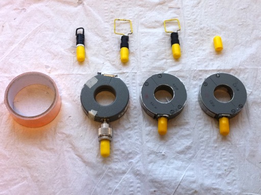
Figure 1. Troubleshooting Toolkit including Current Probes, Wire Loops, and Copper Tape
Abstract: Over the years, I
have developed a tool kit of items that are very useful for circuit
troubleshooting and verification. Components of the kit are discussed
and references given.
Discussion: In addition to the
normal troubleshooting tools like scope probes, oscilloscopes, spectrum
analyzers, and other common measurement hardware, I also have favorite
items I use frequently in my work. Figure 1 shows some of my favorite
troubleshooting tools consisting of a pair of matched F-33-1 current probes, an F-65 current probe, different sizes of square wire loops, and a roll of copper foil tape,
actually "Slug and Snail" tape from the hardware store.
The F-33-1 current probes are very sensitive with a transfer impedance of about five Ohms, that is five Volts/Amp output into 50 Ohms, with a flat frequency response from several MHz to about 300 MHz. They are ideal for measuring common mode currents to predict radiation from system cables. You can read more details on measuring common mode current to predict emissions in my March 2006 Technical Tidbit: Predicting Cable Emissions from Common Mode Current.
The F-65 current probe has a one Ohm transfer impedance, one Volt/Amp, but has a flat frequency response from one MHz to one GHz making this probe ideal for time domain measurement of impulses like ESD using an oscilloscope. One such use of the probe is illustrated in my March 2011 Technical Tidbit: Using High Frequency Measurement of ESD Current to Find Problems with an ESD Simulator.

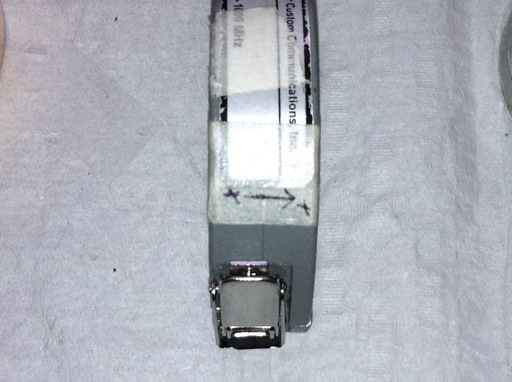
Figure 2. Current Direction for a Positive Output Labeled On Current Probe
Figure 2 shows a tip that helps when using current probes for impulsive
currents. I label the probe for the direction of current that results
in a positive output voltage from the current probe. This trick helps
avoid a lot of turning the current probe around when making impulsive
measurements and in some cases in frequency domain measurements as
well. In Figure 2, I have labeled the direction of current that yields
a positive output on paper tape attached to the probe.
In the upper half of Figure 1, you can see three square magnetic loops made from stiff brass wire and covered with heat shrink tubing. This may be the most useful tool I use! This website is filled with things you can do with such loops from measuring high frequency noise to injecting pulses into circuits for troubleshooting.
Of course, the copper tape shown in Figure 1 is probably in many engineers' tool box. It is useful for modifying circuit cards, shielding, and many other uses. One use is to wrap a cable with a short length of copper tape and discharge an ESD simulator to the copper tape to inject ESD like current capacitively onto just one cable at a time. This technique is described in my January 2009 Technical Tibit: Injection of ESD Current into Cables Using Capacitance. I like to use "Slug and Snail" tape from the hardware store as it is inexpensive and readily available.
The small yellow caps in Figure 1 are actually vacuum port caps for automobile intake manifolds, but make great BNC protectors at very low cost. More information on protecting BNC and SMA connectors this way is in my December 2008 Technical Tidbit: Inexpensive Protective Caps for SMA and BNC Connectors.
The F-33-1 current probes are very sensitive with a transfer impedance of about five Ohms, that is five Volts/Amp output into 50 Ohms, with a flat frequency response from several MHz to about 300 MHz. They are ideal for measuring common mode currents to predict radiation from system cables. You can read more details on measuring common mode current to predict emissions in my March 2006 Technical Tidbit: Predicting Cable Emissions from Common Mode Current.
The F-65 current probe has a one Ohm transfer impedance, one Volt/Amp, but has a flat frequency response from one MHz to one GHz making this probe ideal for time domain measurement of impulses like ESD using an oscilloscope. One such use of the probe is illustrated in my March 2011 Technical Tidbit: Using High Frequency Measurement of ESD Current to Find Problems with an ESD Simulator.

Figure 2. Current Direction for a Positive Output Labeled On Current Probe
In the upper half of Figure 1, you can see three square magnetic loops made from stiff brass wire and covered with heat shrink tubing. This may be the most useful tool I use! This website is filled with things you can do with such loops from measuring high frequency noise to injecting pulses into circuits for troubleshooting.
Of course, the copper tape shown in Figure 1 is probably in many engineers' tool box. It is useful for modifying circuit cards, shielding, and many other uses. One use is to wrap a cable with a short length of copper tape and discharge an ESD simulator to the copper tape to inject ESD like current capacitively onto just one cable at a time. This technique is described in my January 2009 Technical Tibit: Injection of ESD Current into Cables Using Capacitance. I like to use "Slug and Snail" tape from the hardware store as it is inexpensive and readily available.
The small yellow caps in Figure 1 are actually vacuum port caps for automobile intake manifolds, but make great BNC protectors at very low cost. More information on protecting BNC and SMA connectors this way is in my December 2008 Technical Tidbit: Inexpensive Protective Caps for SMA and BNC Connectors.
Summary: Many
people recently have asked me for information on some of the tools I use for
troubleshooting circuits and systems. I have put information on some of
my favorite tools in this Technical Tidbit so that the information is available in one place for easy reference.
Additional articles on this website related to this topic are:
- Current Probes, More Useful Than You Think (~170K)
- (1998 IEEE EMC Symposium paper)
- Signal and Noise Measurement Techniques Using Magnetic Field Probes (~600K)
- (1999 IEEE EMC Symposium paper)
- September 2000, Copper Foil Tape, Anyone?
- December 2005, Applying Copper Foil Tape to a Metal Surface
- March 2006, Predicting Cable Emissions from Common Mode Current
- December 2008, Inexpensive Protective Caps for SMA and BNC Connectors
(also known as vacuum port caps for automobile engines) - January 2009, Injection of ESD Current into Cables Using Capacitance
- March 2011, Using High Frequency Measurement of ESD Current to Find Problems with an ESD Simulator
Need help with a design or additional training on technical subjects? Click on the image below to go to CircuitAdvisor.com, a new engineering resource for training, news, and fun.
If you like the information in this article and others on this website,
much more information is available in my courses. Click here
to see a listing of upcoming courses on design, measurement, and
troubleshooting of chips, circuits, and systems. Click here to see upcoming seminars in Newport Beach, CA.
Click here for a description of my latest seminar titled (now also available online as a WebEx seminar):
EMC
Lab Techniques for Designers
(How to find EMC problems and have some confidence your system will pass EMC testing while it is still in your lab).
(How to find EMC problems and have some confidence your system will pass EMC testing while it is still in your lab).
Home

