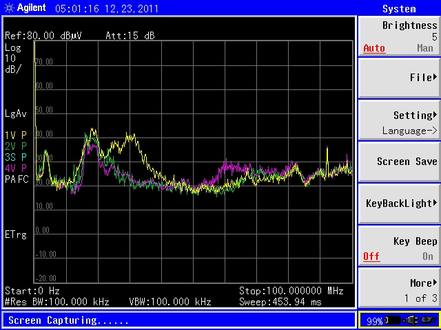
Figure 1. Typical Common Mode Current Plot
(Top of screen = 80 dBuV, Vertical 10 dB/div, Horizontal = 10 MHz/div, Frequency Span from 0 Hz to 100 MHz)
Abstract: EMC testing usually
comes at the end of project development. And when the equipment fails
one of the tests, everything usually grinds to a halt. Often this
results in engineers trying to diagnose the problem at the EMC test
lab. Unless one is lucky, this generally does not produce the desired
results. Use of common mode current measurements on cables is described
and shown to be a powerful method to debug EMC problems as part of an
EMC troubleshooting toolkit.
Discussion: The theory and method of common mode current measurements were discussed in my
March 2006 Technical Tidbit, Predicting Cable Emissions from Common Mode Current.
In this Technical Tidbit, I will discuss why common mode current
measurements are so useful as a troubleshooting technique compared to
troubleshooting at the EMC lab.
There are several reasons that common mode current measurements are useful:
- One can separate the cables (if possible, to minimize coupling
between them) and measure the common mode currents on each separate
cable. By knowing the common mode current on each cable, one can work
on a single cable at a time to find the mechanism generating common
mode current on the cable and fix the problem for that cable. At the
EMC lab, the antenna measures the contribution from all cables and the
equipment, so fixing just one cable may not produce measurable results
when if fact you are making progress. Figure 1 shows common mode
currents on several cables of a system. The 30 dBuV line represents the
amount of common mode current that would just become a problem for
Class B compliance (see the March 2006 Technical Tidbit
for a discussion on this). Clearly the yellow trace is the problem at
30 MHz (third vertical line from the left) where the trace reaches 40
dBuV at that frequency.
- Common mode current measurements can quickly show the effect of
equipment changes on the radiation profile of a cable. In fact, the
plot in Figure 1 could just as easily be three different conditions for
a single cable with the yellow trace being the original common mode
current. The green trace looks like what a common mode choke or ferrite
core on the cable might achieve, and the purple trace looks a lot like
what a grounding change between the circuit board and the chassis might
do.
- Common mode current measurements are so easy you can use them on
early prototype equipment that you would not bother to book time in an
EMC lab for. Using common mode current measurements on early prototypes
can find EMC problems when you have the greatest number of low or no
cost options for fixing the problem.
- Common mode current measurements can allow you to do EMC
troubleshooting in your own lab where you have support equipment and
people available and without EMC lab fees.
A couple of notes on making common mode current measurements:
- Set the spectrum analyzer on "Max Hold" and slide the current
probe slowly down the first meter of cable to catch the current peak.
- Be sure to measure the cable common mode current before you turn
on the equipment to make sure that a nearby radio transmitter or just
lab noise may put too much noise in your cables to measure the
contribution of your equipment. Depending on the size of the equipment
being tested, a basement room or even an empty cube may be quieter than
a development lab. Be suspicious of peaks around 900 or 1800 MHz as
these can easily be a cellphone in the room, although most (but no all)
common mode current related problems are at lower frequencies where the cables are the only system part large enough to radiate.
Check
out my public seminar offering in Boulder City, NV. This is one of the
best seminar values around because the industry typical fee includes
more than just the seminar and lunch, but Lincoln Towne car airport
transportation in NV, lodging in the historic Bouder City Dam Hotel and
Museum, and breakfast and lunch each day. Click here for more details.
Is your product failing ESD testing?
Attend my webinar on sources of error in ESD testing. This webinar
covers problems and mistakes often made in testing products for ESD
compliance that can cause a good product to fail when it should pass.
The webinar is given as both a scheduled event and on-demand. Contact
me at doug@dsmith.org
for more details. Don't let your product fail ESD testing
unnecessarily. This webinar is an easy, cost effective solution.
Need help with a design or additional training on technical subjects? Click on the image below to go to
CircuitAdvisor.com, a new engineering resource for training, news, and
fun.
If you like the information in this article and others on this website,
much more information is available in my courses.
Click here
to see a listing of upcoming courses on design, measurement, and
troubleshooting of chips, circuits, and systems.
Click here to see upcoming seminars in Boulder City, NV.
Click here for a description of my
latest seminar titled (now also available online as a WebEx seminar):
EMC
Lab Techniques for Designers
(How to find EMC problems and have some
confidence your system will pass EMC testing while it is still in your
lab).
Top of page
Home


