Kirchoff and Faraday Voltage Measurements - Don't Confuse Them
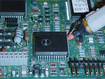
Figure 1. Example of Signal Measurement at a Chip Output, a Kirchoff
Measurement

Address: P. O. Box 1457, Los Gatos,
CA 95031
TEL:
800-323-3956/408-356-4186
FAX:
408-358-3799
Mobile: 408-858-4528
URL:
www.dsmith.org
Email: doug@dsmith.org
Figure 1. Example of Signal Measurement at a Chip Output, a Kirchoff
Measurement
Connection of many measurement instruments to a circuit involves forming a loop. Using a scope probe to make a voltage measurement is an example. The probe tip and ground connection, or the connection of the circuit to the two inputs of a differential probe, must form a loop. This loop can be either more or less important to the results of the measurement depending on the kind of measurement to be made. I divide voltage measurements that use a probe into two categories, which I call Kirchoff or Faraday voltage measurements. Measurements described on this site have included both types and it is time to explicitly explore the implications of these measurements.
In a Kirchoff voltage measurement, so named for Kirchoff's Law that says the sum of voltage drops around a loop equal zero, the measurement is made of a voltage source or signal that does not involve magnetic field effects. Measurement of the output of a gate, similar to that shown in Figure 1, falls into this category. Kirchoff's law says that the source voltage is equal to minus the voltage across the probe since the sum around the loop must be zero. The result is that the position or shape of the loop is not important to the measurement result if the inductive reactance of the measurement loop is much smaller than the probe input impedance.
On the other hand, a Faraday voltage measurement, named for Faraday's Law which says a voltage induced in a loop is proportional to the time changing magnetic flux passing through the loop, involves a voltage that is generated by a time varying magnetic field not a voltage source like a logic gate. An example of this kind of measurement would be a measurement of the Ldi/dt drop across a conductor carrying a high frequency current. One such case is shown in Figure 2 where a differential probe is used to measure the voltage drop across a short length of wire carrying a signal current that is generating an Ldi/dt drop along the wire. The measurement shown in Figure 2 was described in the June 2002 Technical Tidbit on this site titled "Using Mutual Inductance to Measure Voltage Drops in Circuits."
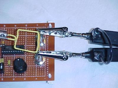
Figure 2. Example of Ldi/dt Voltage Measurement, a Faraday Measurement
In the case of a Faraday voltage measurement, the position and shape of the measurement loop is very important to the result. The probe reads the voltage generated by the time changing magnetic field passing through the loop formed by the probe, its connections to the circuit, and the measured circuit itself. In Figure 2 this includes the current carrying wire and the probe clips and body. We ascribe the result to voltage drop along the wire, but it is really generated in the loop by the time changing magnetic flux passing through the loop. Thus the geometry of the loop is important to the measurement result. If the probe connections were significantly shorter, thus making the measurement loop smaller in Figure 2, a lower voltage reading would likely result as the smaller measurement loop will enclose less of the magnetic flux from the current in the wire.
The voltage measured by a probe in a Faraday measurement generally is not actually seen by any particular circuit element and one must be careful about interpreting the result of such a measurement. For example, if a differential probe is used to measure the drop across the ground plane of a printed wiring board, the measured voltage does not actually appear at any particular gate input. This can be seen with reference to Figure 3 where a source IC is transmitting a signal to a load IC. Let's assume a high frequency noise current is flowing on the ground plane. The noise current generates a magnetic field that affects the signal seen by the load IC as well as the measurement instrument, Vmeas (possibly an oscilloscope).
Figure 3 shows the loop of the ground plane end-to-end voltage measurement as well as the signal loop. The small loop between the signal path and the ground plane will cause the load IC input to see a much smaller voltage due to the ground plane noise current than the measurement instrument will see with its larger loop used to make the measurement. This is so because much of the ground plane noise current's magnetic field field will extend outside of the small loop composed of the signal path and the ground plane. The larger measurement loop will intercept more of the noise induced magnetic field of the ground plane current and will thus result in a larger reading at Vmeas that what the load IC sees. I am assuming that the voltage generated in both loops appears across a high impedance load, either the load IC or the Vmeas instrument.
Figure 3. Comparison of Loops in Voltage Measurement and Signal Transmission
Between Two ICs
So it appears there may not be much of a correlation between the reading of Vmeas and what the load IC input actually sees in this case.
In cases involving high speed electronic circuits, voltage measurements are usually a combination of Kirchoff and Faraday voltage measurements. To the extent that magnetic fields are present that contribute significantly to the result, care must be exercised in the measurement technique and the interpretation of the measurement results. One important source of magnetic fields that find their way into measurements is ESD, electrostatic discharge. Many articles on this website describe ESD effects.
Related measurement articles on this website are: