
Abstract: The following article describes the adaptation of a commercial ESD gun to apply local H-field pulses for troubleshooting sensitive circuits. The key components are a section of brass tubing, some brass strap and a paper clip!
Discussion: In the development/pre-test laboratory a standard commercial ESD gun is rather analogous to a shotgun. When you pull the trigger the product either passes or fails. The two most valuable pieces of knowledge to be developed in the mitigation of a failure are:
- What is the current path of the discharge?
- Which is the most sensitive victim circuit?
 |
 |
| Figure
1 |
Figure
2
|
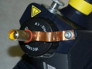
In Figure 1, a simple grounded brass tube extending beyond the tip of the air discharge point is used to produce locally high E-field pulses without discharging directly to sensitive board level components (which is a really good idea if you don’t want to destroy a whole lot of test boards during your investigation). This was the first adaptation of the ESD gun for board level investigations, but its limitations soon became obvious, as noted below. The brass strip from the ESD gun grounding point is held in contact with the brass tube by a rubber O-ring. This allows for quick attachment when changing from normal discharge use to local investigations.
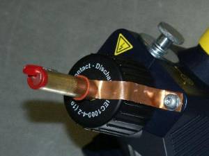
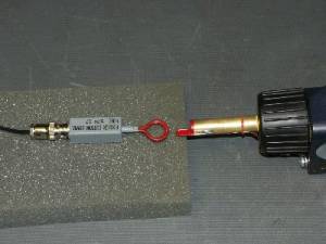
Figure 2 shows the second and generally more useful adaptation. It is simply a paper clip soldered to the same size grounding tube and connects to the point of the contact discharge tip of the ESD gun. The adapter has been dipped in an insulating plastic coating to reduce the risk of shorting board components during the investigation.
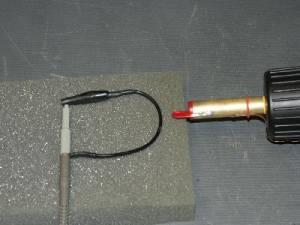
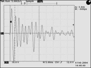
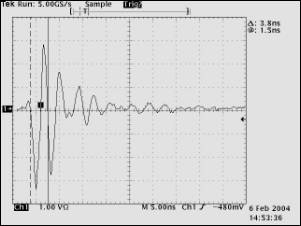
Two examples of the induced H-field interference are shown below. In Figures 3 and 4, the H-field pulse is induced into the ground lead of a 10:1 high impedance oscilloscope probe. Ringing in the scope probe lead makes for a rather poorly behaved waveform, but it is indicative of the kind of voltages that can be developed into a high impedance system. For a “sanity check”, the ground lead was detached from the probe at the lead to probe body end, leaving the tip connected to the lead. The induced voltage to the probe with the loop opened was quite small (<100 mV), indicating that the H-field component was doing the real work.
In Figures 5 and 6, the field is coupled into a Fischer Communications Corporation F-301 near field probe into a 50 ohm terminated input. As would be expected, the waveform shows considerably better damping, but still enough voltage that it could drive against an active logic output hard enough to change the logic level seen by an input.
In both cases, the waveform was recorded by a Tektronix TDS 684B oscilloscope with a 1 GHz analog bandwidth and a 5 GS/sec rate with the ESD gun was set for a 6 kV contact discharge.
 |
 |
| Figure 3 |
Figure 4 (V=10 V/div, H=5 ns/div)
|
 |
 |
| Figure 5 |
Figure 6 (V=1 V/div, H=5 ns/div)
|
Methodology: In both cases it can be seen that the coupled pulses are both quite energetic and fast. By starting at high voltage and a rapid repeat rate (5-10 pulses per second), you can find the general area of the sensitivity quickly. Then begin stepping down the voltage and change to single discharge to more finely localize the sensitive circuit. This is where the H-field version has significant advantage over the E-field version. At low voltages it is much more difficult to create a consistent air discharge induced field into the circuit.
Conclusion: This very simple accessory for a standard ESD gun can provide a useful troubleshooting tool that can be used with cables, back planes, board traces and individual components to identify ESD sensitive victim circuits.