
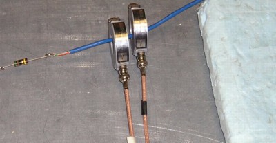
Figure 1. Current Probes on Cat 5 Cable Carrying EFT Current
Abstract: Significant sources of
error can exist in voltage and current probes that are often not
explicitly spelled out in specifications. Verification of measurements
is
absolutely necessary before decisions are made based on measurement
results. Two methods of verifying current
measurements are described and experimental results presented that
build on a previous Technical Tidbit article.
Discussion: The January 2000 Technical Tidbit on this site titled "Displaying Measurement Error" addressed sources of error, specifically in current measurements. This article presents new data, discusses sinusoidal signals, and presents an additional method of verification that does not require a second matched probe.
Figure 1 shows two matched Fischer F-33-1 current probes placed on a Cat 5 ethernet cable four meters in length. An electrical fast transient burst generator, EFT, was used to generate high frequency current pulses on the cable using a "capacitive clamp." The EFT generator conformed to IEC 61000-4-4, the standard defining EFT and how to test equipment with it. Terminations of 150 Ohms were used on both ends of the Cat 5 cable. One of three series 51 Ohm resistors can be seen in Figure 1. This setup is similar to the January 2000 Technical Tidbit except that this setup is more realistic using a Cat 5 cable of nominal length as opposed to a short wire.
Many current probes on the market are designed for low impedance 50 Ohm RF environments where there is significant current for relatively small voltages (and relatively low electric fields). EFT currents, as well as those produced by ESD, are often accompanied by significant electric fields as well so it is necessary to verify electric field response of current probes used to measure currents arising from EFT or ESD.
Figure 2 shows the output from the two probes in Figure 1 indicating a current of about 1/2 Ampere for a generator setting of 250 Volts, a relatively low value compared to the capabilities of the generator that usually exceed 4 kV. One would think that since the two waveforms in Figure 2 look close to the same, the two probes are working properly. However, results like those in Figure 2 are not sufficient to validate current probe performance. One additional test is needed. I call this a "null experiment."
Figure 2. Output from Current Probes on Cat 5 Cable in same Orientation
Figure 3 shows the outputs of the same current probes when one of
them has been reversed on the cable. If the output of the probes were
only dependent on the current flowing through them, actually the
magnetic field generated by the current, the probe that is reversed
should show an output that is a mirror image of the other probe's
output. Current is flowing in the opposite direction through the
reversed probe.
Figure 3. Output from Current Probes on Cat 5 Cable with One Probe Reversed
Summary: Verification of current probe measurements is imperative, especially when the probes are used in circuits with impedances higher than 50 Ohms. Using matched current probes, with one reversed, and adding the outputs provides a way to verify the whole measurement chain. Folding the cable and inserting it into a current probe provides an alternate method to verify results that does not require a second matched probe.
Discussion: The January 2000 Technical Tidbit on this site titled "Displaying Measurement Error" addressed sources of error, specifically in current measurements. This article presents new data, discusses sinusoidal signals, and presents an additional method of verification that does not require a second matched probe.
Figure 1 shows two matched Fischer F-33-1 current probes placed on a Cat 5 ethernet cable four meters in length. An electrical fast transient burst generator, EFT, was used to generate high frequency current pulses on the cable using a "capacitive clamp." The EFT generator conformed to IEC 61000-4-4, the standard defining EFT and how to test equipment with it. Terminations of 150 Ohms were used on both ends of the Cat 5 cable. One of three series 51 Ohm resistors can be seen in Figure 1. This setup is similar to the January 2000 Technical Tidbit except that this setup is more realistic using a Cat 5 cable of nominal length as opposed to a short wire.
Many current probes on the market are designed for low impedance 50 Ohm RF environments where there is significant current for relatively small voltages (and relatively low electric fields). EFT currents, as well as those produced by ESD, are often accompanied by significant electric fields as well so it is necessary to verify electric field response of current probes used to measure currents arising from EFT or ESD.
Figure 2 shows the output from the two probes in Figure 1 indicating a current of about 1/2 Ampere for a generator setting of 250 Volts, a relatively low value compared to the capabilities of the generator that usually exceed 4 kV. One would think that since the two waveforms in Figure 2 look close to the same, the two probes are working properly. However, results like those in Figure 2 are not sufficient to validate current probe performance. One additional test is needed. I call this a "null experiment."
Figure 2. Output from Current Probes on Cat 5 Cable in same Orientation
Figure 3. Output from Current Probes on Cat 5 Cable with One Probe Reversed
Looking at Figure 3, one can see that is
the case. If the two waveforms are added in the scope, the result
should
be nearly zero, hence the name "null experiment." As obvious as this
seems, I have seen many current
probes where the two waveforms would look significantly different due
to electric field coupling through inadequate probe
shielding. Electric field, capacitive, coupling into a current
probe results in an output that would not depend strongly on which
direction the probe is placed on a cable. When this is added to the
probe current response that inverts when the probe is reversed, the
result would be that the
inverted waveform would have a different shape and the sum of the two
waveforms in Figure 3 would not add to zero.
The same effect would hold for sinusoidal currents. When measuring sinusoidal currents, the output of two current probes could be added in a combiner with one probe reversed on the cable. To the extent the output of the combiner differs from zero, electric field coupling is likely affecting the current probes (assuming the probes are really matched and other links in the measurement chain are working as intended). A spectrum analyzer can be used in this case as well as a scope since the combiner provides a single output. Spectrum analyzers have a much wider dynamic range than an oscilloscope, so the outcome of the null experiment often is a result of the combiner's accuracy.
A method of verifying current probe operation not requiring a second matched probe is shown in Figure 4. In this case, the cable is folded and inserted into the current probe. Doing this exposes the current probe to the electric field from the cable, but no current actually flows through the probe so its output should be zero. Figure 5 shows the result of such a measurement.
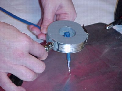
The current on the cable that produced the "null experiment" result of Figure 4 had an amplitude of about one Ampere, so the ~100 mA error in the measurement was on the order of 10%. The current measurement itself used the current probe right on the ground plane so the electric field and resulting error would likely have been less than shown in Figure 4.
The "folded wire" null experiment checks the current probe electrical field response only. It does not check the probe cable or other elements of the measurement chain the way using two matched probes does. For the sum of the two probes (one reversed) to add to zero, everything in the measurement chain must be working properly: the current probes, cables, connectors, and oscilloscope vertical amplifiers.
Being able to check electric field induced error with only the current probe used for the measurement is important at frequencies over a few hundred megahertz. Above that, matching of probes becomes increasingly difficult if not impossible.
In my experience, many current probes have significant electric field response. The Fischer F-33-1 probes used for the measurements in this article are among the best current probes available for rejection of electric fields. I have seen other current probes with an error due to electric field effects on the order of 50%. A number of popular commercial current probes have electric field induced errors on the order of 25% for common measurement configurations.
The same effect would hold for sinusoidal currents. When measuring sinusoidal currents, the output of two current probes could be added in a combiner with one probe reversed on the cable. To the extent the output of the combiner differs from zero, electric field coupling is likely affecting the current probes (assuming the probes are really matched and other links in the measurement chain are working as intended). A spectrum analyzer can be used in this case as well as a scope since the combiner provides a single output. Spectrum analyzers have a much wider dynamic range than an oscilloscope, so the outcome of the null experiment often is a result of the combiner's accuracy.
The Folded Wire Null Experiment
A method of verifying current probe operation not requiring a second matched probe is shown in Figure 4. In this case, the cable is folded and inserted into the current probe. Doing this exposes the current probe to the electric field from the cable, but no current actually flows through the probe so its output should be zero. Figure 5 shows the result of such a measurement.
Figure 4. Folded Wire Null Experiment
Figure 5. Folded Wire Null Experiment Result
The current on the cable that produced the "null experiment" result of Figure 4 had an amplitude of about one Ampere, so the ~100 mA error in the measurement was on the order of 10%. The current measurement itself used the current probe right on the ground plane so the electric field and resulting error would likely have been less than shown in Figure 4.
The "folded wire" null experiment checks the current probe electrical field response only. It does not check the probe cable or other elements of the measurement chain the way using two matched probes does. For the sum of the two probes (one reversed) to add to zero, everything in the measurement chain must be working properly: the current probes, cables, connectors, and oscilloscope vertical amplifiers.
Being able to check electric field induced error with only the current probe used for the measurement is important at frequencies over a few hundred megahertz. Above that, matching of probes becomes increasingly difficult if not impossible.
In my experience, many current probes have significant electric field response. The Fischer F-33-1 probes used for the measurements in this article are among the best current probes available for rejection of electric fields. I have seen other current probes with an error due to electric field effects on the order of 50%. A number of popular commercial current probes have electric field induced errors on the order of 25% for common measurement configurations.
Summary: Verification of current probe measurements is imperative, especially when the probes are used in circuits with impedances higher than 50 Ohms. Using matched current probes, with one reversed, and adding the outputs provides a way to verify the whole measurement chain. Folding the cable and inserting it into a current probe provides an alternate method to verify results that does not require a second matched probe.
I would like to thank and acknowledge Elliott Laboratories of Sunnyvale, CA for the use of their facilities to take some of the data in this article.
Other articles on this website related to this topic are:
- June 1999: The Dual Current Probe Problem
- July 1999: The Shorted Scope Probe Problem (example of another null experiment)
- September 1999: Measuring Voltages Using Current Probes
- January 2000: Displaying Measurement Error
- An Investigation into the Performance of the IEC 1000-4-4 Capacitive Clamp (~150K pdf file)
- Current Probes, More Useful Than You Think (~170K pdf file)
If you like the information in this article and others on this website, much more information is available in my courses. Click here to see a listing of upcoming courses on design, measurement, and troubleshooting of chips, circuits, and systems.
Coming soon: my new one day seminar titled: Failure Analysis and Prevention in Electronic Circuits (Design Troubleshooting for the Lab and Field).
Equipment used in this article includes:
Top of page
Home