
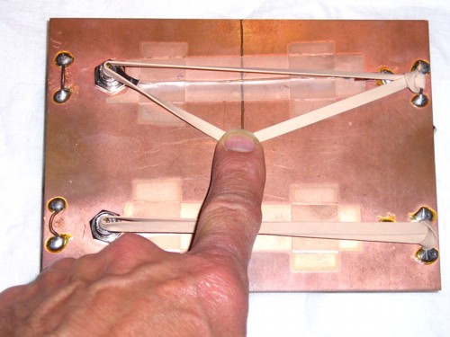
Figure 1. Circuit Board With Rubber Bands Stretched Along Signal Paths
Abstract: Having a simple way of
explaining circuit operation can be helpful for a designer trying to
explain to a boss or coworker why a board design must be done a certain
way. A very simple example of using rubber bands to illustrate the
effect of a ground plane break is discussed and related to other
circuit constructions such as pigtail connection of cable shields. This
article also serves as an index to five articles on this site that discuss the
effects of crossing a signal path over a break in a ground plane.
Discussion: Figure 1 shows two
rubber bands stretched over two signal paths of a test board that is used in
several Technical Tidbit articles on this website. In some sense, the
rubber bands serve to illustrate how a signal loop is affected by a
break in a ground plane. The signal path at the bottom of the board is
over a solid ground plane. All signal paths define a loop, from source
to load and back again. In the lower path in Figure 1, the signal path
extends from the BNC connector to a 47 Ohm resistor on the right (hidden
by the rubber band). The signal returns by the path of least impedance,
which at frequencies much above tens of kHz is the path of least
inductance. This is right under the signal path in the ground plane.
The current in the ground plane spreads out somewhat, but not much,
being confined mostly to a few widths of the signal path in the ground
plane.
The two sides of the rubber band loop also are very close to each other because force is needed to stretch the bands further apart, much like the electrical signal path.
In the upper path, the signal loop extends from the BNC connector to the 47 Ohm load on the right (partially obscured by the rubber band), The signal returns over the path of least inductance as before, but this time it is forced around the end of the ground plane break. The returning signal current will stay near the signal to load path until close to the break and then follow the break closely around its end and back to the signal path, opening a much larger loop between the two sides of the signal loop than without the break. The signal to load path and the returning path in the ground plane now define a good sized loop which has all manner of unpleasant effects on circuit operation. Five Technical Tidbit articles on this site describe some of these effects and are linked at the end of this article. The unintended effects of the ground break include: crosstalk, lowered immunity to EMI, increased emissions, and slowing of the signal risetime.
The upper rubber band in Figure 1 acts in a similar manner. The two halves of the rubber band want to be close to each other. Force is required to separate them and pull one half of the rubber band to the end of the ground break. The rubber band would like to snap into place again, but is being held apart, defining a large loop. The force holding the rubber band at the end of the ground break is like the increased loop inductance in the signal loop of the electrical signal. The current really wants to have the two parts of its loop close to each other to minimize inductance. The difference between the two cases is that the current hugs the ground break whereas the rubber band forms a triangle. But the analogy is good enough for a manager.
Figure 2 shows another example of forcing a signal return away from the signal path, a pigtail connection of a shield. If you connect a coaxial cable using the device in Figure 2, it is not difficult using a three Volt, 30 MHz square wave with a two nanosecond risetime to exceed emission limits by 40+ dB. If the device of Figure 2 is inserted in a coaxial cable of any cost, the shielding performance of the coaxial cable will likely be worst than the cheapest cable you can buy without the device inserted.
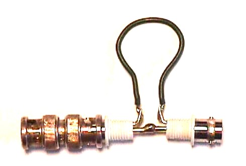
Figure 2. Pigtail Connection of a Coax Shield
The two sides of the rubber band loop also are very close to each other because force is needed to stretch the bands further apart, much like the electrical signal path.
In the upper path, the signal loop extends from the BNC connector to the 47 Ohm load on the right (partially obscured by the rubber band), The signal returns over the path of least inductance as before, but this time it is forced around the end of the ground plane break. The returning signal current will stay near the signal to load path until close to the break and then follow the break closely around its end and back to the signal path, opening a much larger loop between the two sides of the signal loop than without the break. The signal to load path and the returning path in the ground plane now define a good sized loop which has all manner of unpleasant effects on circuit operation. Five Technical Tidbit articles on this site describe some of these effects and are linked at the end of this article. The unintended effects of the ground break include: crosstalk, lowered immunity to EMI, increased emissions, and slowing of the signal risetime.
The upper rubber band in Figure 1 acts in a similar manner. The two halves of the rubber band want to be close to each other. Force is required to separate them and pull one half of the rubber band to the end of the ground break. The rubber band would like to snap into place again, but is being held apart, defining a large loop. The force holding the rubber band at the end of the ground break is like the increased loop inductance in the signal loop of the electrical signal. The current really wants to have the two parts of its loop close to each other to minimize inductance. The difference between the two cases is that the current hugs the ground break whereas the rubber band forms a triangle. But the analogy is good enough for a manager.
Figure 2 shows another example of forcing a signal return away from the signal path, a pigtail connection of a shield. If you connect a coaxial cable using the device in Figure 2, it is not difficult using a three Volt, 30 MHz square wave with a two nanosecond risetime to exceed emission limits by 40+ dB. If the device of Figure 2 is inserted in a coaxial cable of any cost, the shielding performance of the coaxial cable will likely be worst than the cheapest cable you can buy without the device inserted.
Figure 2. Pigtail Connection of a Coax Shield
Summary: Forcing a signal current apart from its returning
component to define a larger loop can cause many circuit problems including
excess crosstalk and emissions as well as lowering of immunity
to EMI and slowing signal rising edges. The rubber band analogy is a
simple way of thinking of the problem. Just think of the signal to load
current and the load to signal current trying to snap back together.
Other articles on this website related to this topic are:
- December 2002, Crossing Ground Plane Breaks, A Source of Crosstalk
- January 2003, Crossing Ground Plane Breaks - Part 2, Tracing Current Paths
- February 2003, Crossing Ground Plane Breaks - Part 3, Immunity to Radiated EMI
- January 2005, Crossing Ground Plane Breaks - Part 4, Risetime Effects on Signals
- February 2005, Crossing Ground Plane Breaks - Part 5, Common Mode Currents and Emissions
Click here for a description of my latest seminar to be available soon titled:
EMC
Lab Techniques for Designers
(How to find EMC problems and have some confidence your system will pass EMC testing while it is still in your lab).
(How to find EMC problems and have some confidence your system will pass EMC testing while it is still in your lab).
 |
Check out my podcast containing mp3 format short tutorials, tech news and more! Just click on the microphone to see the listing
of free
audio programs. Content is added every week on technical topics so check back frequently. |
Home