
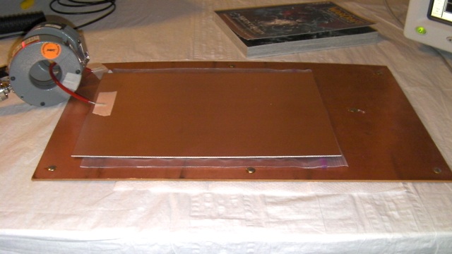
Figure 1. Test Setup For Measuring The Resonance of Two Copper-clad Boards Connected by a Wire
Abstract: When circuit boards
are connected by conductors, a resonant circuit results from the
inductance of the conductors and the capacitance between the circuit
boards. A simple way to damp such board resonances is discussed. The method
can be very useful if the designer is restricted to only one connection
point between two boards and applies both to a pair of boards or a single board mounted over a metal chassis.
Discussion: Figure 1 shows the
test setup used for this Technical Tidbit. The test setup was also used in the January 2010 Technical Tidbit
on this site where the focus was on measuring the resonance of the
boards. For this article, the focus is how do damp the resonance that
results when two boards (or one board and a chassis) are connected by conductors.
The setup is composed of two copper-clad boards connected by a wire about four inches (~10 cm) long, a Fischer TG-EFT pulse generator, two current probes, and a scope. The two boards are separated about one mm by a plastic bag. One current probe, a Fischer F-62b, was used to inject pulses and the other, a Fischer F-65, was used to monitor the current. The setup is described in more detail in the January 2010 Technical Tidbit on this site.
Figure 2 shows the measured current in response to the injected pulse from the Fischer TG-EFT generator. Note the ringing on the current waveform at about 34 MHz has an amplitude of about 500 mA. This data was presented in the January 2010 Technical Tidbit but the question now is what to do about it. One could connect the boards at multiple points to reduce the inductance between the boards and thus raising the resonant frequency, hopefully high enough to not be a problem. But sometimes, just moving the resonant frequency of a structure is not enough or a designer is constrained to connect two circuit boards at only one location. What can one do then about the resonance?
One possible answer is shown in Figure 3. A resistor is connected between the two copper-clad boards. Figures 4, 5, and 6 show the resulting current waveforms that resulted for resistor valuses of 360, 51, and 22 Ohms respectively. Note that 360 Ohms provides some damping and 51 Ohms more, but 22 Ohms damped the ringing in less than one cycle. The initial peak is about the same in all cases, just the damping has been changed by the resistor value.
The data suggests that the capacitive reactance between the copper-clad boards and the inductive reactance of the wire between them is about 20 to 30 Ohms, a typical value encountered when mounting a circuit board over a metal chassis at resonance. In that case, the larger copper clad board in Figure 1 becomes the chassis.
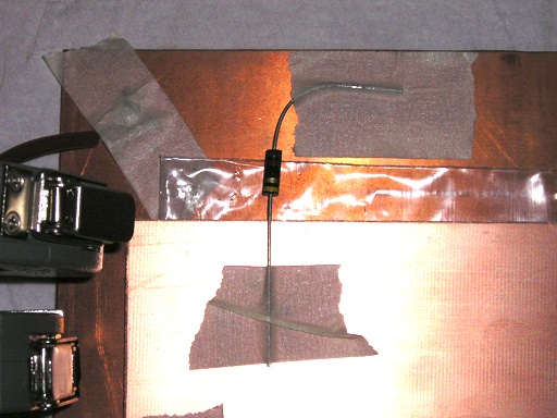
Figure 4. Current Measured Between Two Copper-clad Boards at 1 mm Spacing With 360 Ohm Damping Resistor
(Vertical scale = 200 mA/div, Horizontal scale = 20 ns/div)

Figure 5. Current Measured Between Two Copper-clad Boards at 1 mm Spacing With 51 Ohm Damping Resistor
(Vertical scale = 200 mA/div, Horizontal scale = 20 ns/div)
A slight variation of the experiment is shown in Figure 7 where the resistor has been moved to the opposite side of the boards from the current probes and pulse injection. Figure 8 shows the result.
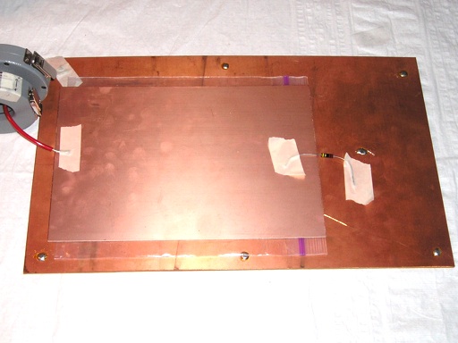
Figure 7. Test Setup Modified to Place the Damping Resistor Opposite the Current Probes

Figure 8. Current Measured Between Two Copper-clad Boards at 1 mm Spacing With 22 Ohm Damping Resistor Opposite Current Probes
(Vertical scale = 200 mA/div, Horizontal scale = 20 ns/div)
The setup is composed of two copper-clad boards connected by a wire about four inches (~10 cm) long, a Fischer TG-EFT pulse generator, two current probes, and a scope. The two boards are separated about one mm by a plastic bag. One current probe, a Fischer F-62b, was used to inject pulses and the other, a Fischer F-65, was used to monitor the current. The setup is described in more detail in the January 2010 Technical Tidbit on this site.
Figure 2 shows the measured current in response to the injected pulse from the Fischer TG-EFT generator. Note the ringing on the current waveform at about 34 MHz has an amplitude of about 500 mA. This data was presented in the January 2010 Technical Tidbit but the question now is what to do about it. One could connect the boards at multiple points to reduce the inductance between the boards and thus raising the resonant frequency, hopefully high enough to not be a problem. But sometimes, just moving the resonant frequency of a structure is not enough or a designer is constrained to connect two circuit boards at only one location. What can one do then about the resonance?
Figure 2. Current Measured Between Two Copper-clad Boards at 1 mm Spacing
(Vertical scale = 200 mA/div, Horizontal scale = 20 ns/div)
(Vertical scale = 200 mA/div, Horizontal scale = 20 ns/div)
One possible answer is shown in Figure 3. A resistor is connected between the two copper-clad boards. Figures 4, 5, and 6 show the resulting current waveforms that resulted for resistor valuses of 360, 51, and 22 Ohms respectively. Note that 360 Ohms provides some damping and 51 Ohms more, but 22 Ohms damped the ringing in less than one cycle. The initial peak is about the same in all cases, just the damping has been changed by the resistor value.
The data suggests that the capacitive reactance between the copper-clad boards and the inductive reactance of the wire between them is about 20 to 30 Ohms, a typical value encountered when mounting a circuit board over a metal chassis at resonance. In that case, the larger copper clad board in Figure 1 becomes the chassis.
Figure 3. Close-up View Showing a Resistor Connecting the Two Copper-clad Boards
Figure 4. Current Measured Between Two Copper-clad Boards at 1 mm Spacing With 360 Ohm Damping Resistor
(Vertical scale = 200 mA/div, Horizontal scale = 20 ns/div)
Figure 5. Current Measured Between Two Copper-clad Boards at 1 mm Spacing With 51 Ohm Damping Resistor
(Vertical scale = 200 mA/div, Horizontal scale = 20 ns/div)
Figure 6. Current Measured Between Two Copper-clad Boards at 1 mm Spacing With 22 Ohm Damping Resistor
(Vertical scale = 200 mA/div, Horizontal scale = 20 ns/div)
(Vertical scale = 200 mA/div, Horizontal scale = 20 ns/div)
A slight variation of the experiment is shown in Figure 7 where the resistor has been moved to the opposite side of the boards from the current probes and pulse injection. Figure 8 shows the result.
Figure 7. Test Setup Modified to Place the Damping Resistor Opposite the Current Probes
Figure 8. Current Measured Between Two Copper-clad Boards at 1 mm Spacing With 22 Ohm Damping Resistor Opposite Current Probes
(Vertical scale = 200 mA/div, Horizontal scale = 20 ns/div)
The waveform in Figure 8 is
essentially the same as in Figure 6. Placing the resistor on the
opposite end of the board made no difference. This is to be expected when
the size of the boards are small compared to the wavelength at the
frequency of interest, 34 MHz in this example.
The resistor could have been added
directly in parallel with the wire connecting the two boards with the
same result. This technique can be used to damp board resonance when
the board is constrained to a single point of connection to another
board or a system chassis.
Summary:
Current probes and pulse injection were used to investigate the
resonance between a circuit board and nearby metal (chassis or another
board) connected by a conductor. In particular, the resulting resonance was shown to be damped
by a resistor of a few tens of Ohms between the circuit board and
the nearby metal. The damping was independent of the position of the
resistor because the copper-clad boards used were small in comparison
to a wavelength at the 34 MHz resonant frequency of this example.
Additional articles on this website related to this topic are:
- Current Probes, More Useful
Than You Think (~170K)
(1998 IEEE EMC Symposium paper) - January 2006, A Small Change Can Have a Large Effect
- October 2007, Using Noise Injection for Troubleshooting Circuits
- November 2007, Measuring Structural Resonances in the Time Domain - Part 1
- December 2007, Using Current Probes to Inject Pulses for Troubleshooting
(Current Probes, More Useful Than You Think - Part 2) - March 2009, Using Current Probes to Inject Pulses for Troubleshooting - Part 2
(Current Probes, More Useful Than You Think - Part 3) - April 2009, Construction of a Series 50 Ohm Termination
- May 2009, Using a Series 50 Ohm Termination With a High Voltage Transient Generator
- January 2010, Using Current Probes to Inject Pulses for Troubleshooting (Board Resonances) - Part 3
(Current Probes, More Useful Than You Think - Part 4)
- The scope used in this Technical Tidbit is an Agilent Infinium 54845a scope
- Fischer Custom Communications F-62b and F-65 current probes
- Fischer Custom Communications TG-EFT high voltage pulse generator
Click here for a description of my latest seminar titled (now also available online as a WebEx seminar):
EMC
Lab Techniques for Designers
(How to find EMC problems and have some confidence your system will pass EMC testing while it is still in your lab).
(How to find EMC problems and have some confidence your system will pass EMC testing while it is still in your lab).
 |
Check
out my new site, CircuitAdvisor.com containing tutorials, tech news and
more! Just click on the
microphone to go there. Content is added every week on technical
topics so check back frequently. |
Home