
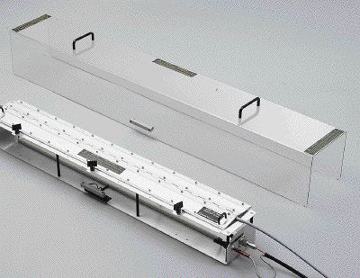
Figure 1. An IEC 61000-4-4 Capacitive Clamp
Abstract: Analysis is performed of the
currents injected by the IEC 61000-4-4 Capacitive Clamp using current
probes. Surprising results of the current measurements indicate that the Capacitive
Clamp is directional and sends more energy to the support equipment (AUX) than to the equipment
under test (EUT)! The directional property of the Capacitive Clamp also leads to a common lab
error where significantly more energy is applied to the EUT if the
clamp is not properly connected, potentially
causing compliant equipment to fail the test.
Discussion: Figure 1 shows a typical IEC 61000-4-4 Capacitive Clamp that is used to inject electrical fast transient (EFT) noise on I/O leads of equipment. The clamp is symmetrical and can be fed by the EFT generator from either end. The January 2000 Technical Tidbit on this site titled "Displaying Measurement Error" discusses how incident and reflected waves on the clamp can cause more energy to exit the clamp on the end opposite to the generator connection, The data presented in this article covers a more realistic case and its implications.
The experimental setup is shown in Figure 2. A four meter Cat 5 data cable is positioned in the Capacitive Clamp and 150 Ohm terminations are placed at the ends of the cable. All the conductors are connected together in common mode. Figure 3 shows the detail of the one of the terminations and its connections to the Cat 5 cable. In the IEC 61000-4-4 standard, the EFT generator is to be connected to the side of the symmetrical Capacitive Clamp that is closest to the EUT. In Figure 2, that defines the termination on the right as the "EUT" and the termination on the left as the "AUX equipment."
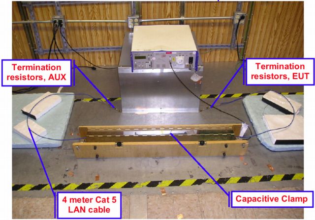
Figure 2. Experimental Setup
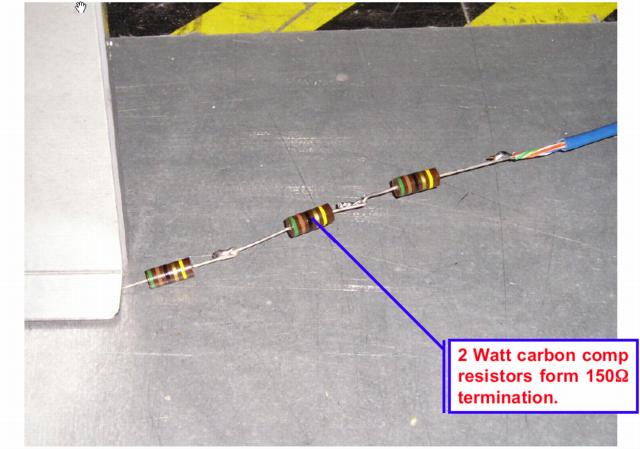
Figure 4 shows the current flowing in the terminations of Figure 2 when EFT is supplied from the generator. For the measurements, a pair of matched Fischer F-33-1 current probes were placed on the Cat 5 cable near the terminations in the same orientation (same face of each probe to the right). This produces opposite current directions in the probes so their outputs are inverted with respect to each other. See the April 2005 Technical Tidbit, "Inductive and Capacitive Coupling - Induced Current Characteristics" for an explanation of why the current should be in opposite directions as far as the current probes are concerned.
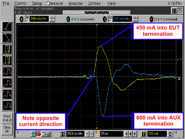
Figure 4. Output from Current Probes on Cat 5 Cable in same Orientation
The surprising result shown in Figure 4 is that about one third
more current is directed to the AUX end of the cable than to the EUT
end. This result is consistent with results from the January 2000
Technical Tidbit on this site titled "Displaying Measurement Error."
The more realistic test setup shown in Figure 2 produces slightly
different results than the January 2000 article, although with the same
conclusions. The data in Figure 4 suggests that the Capacitive Clamp
may be specified backwards in the standard. The generator level used in
this experiment was low, a few hundreds of Volts, so as not to overload the
scope inputs or require external attenuators on the scope.
Summary: The Capacitive Clamp used in IEC 61000-4-4 delivers significantly more current to the auxiliary support equipment than the equipment under test. It appears that the Capacitive Clamp connections may be specified backwards in the standard. A common error I have seen made by test labs is to connect the generator to the wrong end of the clamp. This error turns the EUT into the AUX equipment and over tests the EUT. Such a condition can potentially fail a compliant EUT.
Discussion: Figure 1 shows a typical IEC 61000-4-4 Capacitive Clamp that is used to inject electrical fast transient (EFT) noise on I/O leads of equipment. The clamp is symmetrical and can be fed by the EFT generator from either end. The January 2000 Technical Tidbit on this site titled "Displaying Measurement Error" discusses how incident and reflected waves on the clamp can cause more energy to exit the clamp on the end opposite to the generator connection, The data presented in this article covers a more realistic case and its implications.
The experimental setup is shown in Figure 2. A four meter Cat 5 data cable is positioned in the Capacitive Clamp and 150 Ohm terminations are placed at the ends of the cable. All the conductors are connected together in common mode. Figure 3 shows the detail of the one of the terminations and its connections to the Cat 5 cable. In the IEC 61000-4-4 standard, the EFT generator is to be connected to the side of the symmetrical Capacitive Clamp that is closest to the EUT. In Figure 2, that defines the termination on the right as the "EUT" and the termination on the left as the "AUX equipment."
Figure 2. Experimental Setup
Figure 3. 150 Ohm Cable Termination
Figure 4 shows the current flowing in the terminations of Figure 2 when EFT is supplied from the generator. For the measurements, a pair of matched Fischer F-33-1 current probes were placed on the Cat 5 cable near the terminations in the same orientation (same face of each probe to the right). This produces opposite current directions in the probes so their outputs are inverted with respect to each other. See the April 2005 Technical Tidbit, "Inductive and Capacitive Coupling - Induced Current Characteristics" for an explanation of why the current should be in opposite directions as far as the current probes are concerned.
Figure 4. Output from Current Probes on Cat 5 Cable in same Orientation
I have
personally seen many test labs connect the Capacitive Clamp to the
generator on the end opposite the EUT. This essentially turns the EUT
into the AUX equipment and therefore applies more current to the EUT
than the IEC 61000-4-4 standard calls for. In some cases, I have seen
much more than the 30% additional current in the data above
(depending on equipment impedances) delivered to the EUT.
The error in the test setup is easy to understand. The clamp is one meter long and a one meter cable is specified to connect it to the EFT generator which itself is often bolted to the metal test floor. This setup can often make it difficult to connect the clamp on the proper end. If your equipment fails this test, be sure to look carefully at the test setup pictures in the test report! Maybe your equipment really passed.
The error in the test setup is easy to understand. The clamp is one meter long and a one meter cable is specified to connect it to the EFT generator which itself is often bolted to the metal test floor. This setup can often make it difficult to connect the clamp on the proper end. If your equipment fails this test, be sure to look carefully at the test setup pictures in the test report! Maybe your equipment really passed.
Summary: The Capacitive Clamp used in IEC 61000-4-4 delivers significantly more current to the auxiliary support equipment than the equipment under test. It appears that the Capacitive Clamp connections may be specified backwards in the standard. A common error I have seen made by test labs is to connect the generator to the wrong end of the clamp. This error turns the EUT into the AUX equipment and over tests the EUT. Such a condition can potentially fail a compliant EUT.
I would like to thank and acknowledge Elliott Laboratories of Sunnyvale, CA for the use of their facilities to take the data presented in this article and Thermo Electron Corporation for the picture of the KeyTek Capacitive Clamp in Figure 1.
Other articles on this website related to this topic are:
- June 1999: The Dual Current Probe Problem
- July 1999: The Shorted Scope Probe Problem (example of another null experiment)
- September 1999: Measuring Voltages Using Current Probes
- January 2000: Displaying Measurement Error
- April 2005, Inductive and Capacitive Coupling - Induced Current Characteristics
- May 2005: Verifying Current Measurements - Revisited
- An Investigation into the Performance of the IEC 1000-4-4 Capacitive Clamp (~150K pdf file)
- Current Probes, More Useful Than You Think (~170K pdf file)
If you like the information in this article and others on this website, much more information is available in my courses. Click here to see a listing of upcoming courses on design, measurement, and troubleshooting of chips, circuits, and systems.
Coming soon: my new one day seminar titled: Failure Analysis and Prevention in Electronic Circuits (Design Troubleshooting for the Lab and Field).
Measurement equipment used to take the data for this article includes:
Top of page
Home