
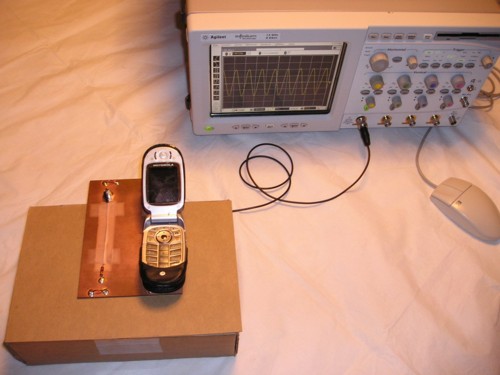
Figure 1. Test Setup With Mobile Phone in Proximity to a Test Board
Abstract: Cases of circuit
failures caused by mobile, or cell, phones are starting to be reported.
Electromagnetic Interference (EMI) from mobile phones has been shown to produce hard and
soft failures in circuits. Data is presented to show the possible
amplitude
of EMI induced into a common printed wiring board layout feature.
The induced signal is of sufficient amplitude to corrupt signals and in
some cases cause hard failures.
Discussion: Figure 1 shows the
test setup used. A mobile phone is placed on top of a test board,
directly over a path that crosses a ground plane break, an undesirable
layout feature (see links about this at the bottom of this page). The
data was taken during an active phone call.
The test board was constructed as shown in Figure 2, and has been used in several Technical Tidbit articles on this website. The signal paths on the board are formed from 24 AWG bare wires taped to an insulating layer of tape over the board surface. Each path runs from a BNC connector to a 47 Ohm termination. One path stays over solid ground while the other crosses a 5 cm ground plane break. Only the latter was used for this test.
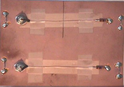
Figure 2. Test Board Used in Experiment
The test board was constructed as shown in Figure 2, and has been used in several Technical Tidbit articles on this website. The signal paths on the board are formed from 24 AWG bare wires taped to an insulating layer of tape over the board surface. Each path runs from a BNC connector to a 47 Ohm termination. One path stays over solid ground while the other crosses a 5 cm ground plane break. Only the latter was used for this test.
Figure 2. Test Board Used in Experiment
One cannot usually control the power level (~600 mW maximum) or frequency (~900
MHz or ~1800 MHz) of a mobile phone without special equipment as those
parameters are set by the mobile network base station the phone is
connected to. In this case, the phone was operating in the US ~900 MHz
band. The indicated signal strength was low (two of five bars) so the phone
should have been near, but not necessarily at, its maximum power.
Figure 3 shows a side view of the test setup. The phone was placed over the path crossing the ground break so as to maximize the EMI generated in the path. Remember Murphy's Law! If the phone protective cover had been removed to allow closer spacing to the board, the induced EMI would have been larger than that observed.
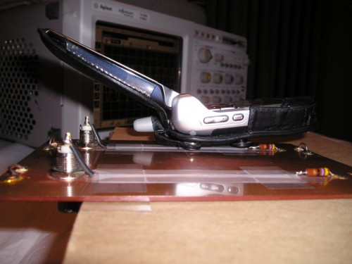
Figure 3. Side View of Test Setup
Figure 4 shows the mobile phone next to the board to get a clear view of both the phone and board.
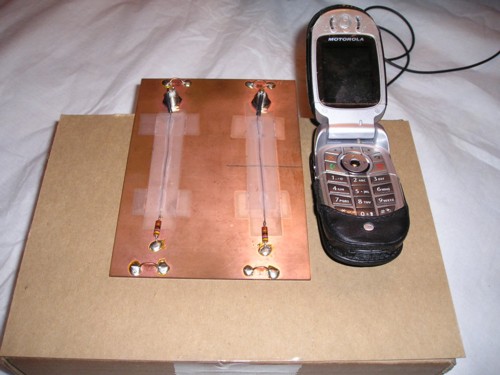
Figure 5 shows the resulting scope plot. The period of the sine wave was a little over one nanosecond with a peak amplitude of over two Volts! An amplitude of two Volts peak into the 50 Ohm termination in the scope is certainly enough to cause effects on real circuits. There is about 40 mW of power delivered to the scope and also to the 47 Ohm termination, a total of about 80 mW. This is a significant fraction of the phone's transmitting power.
Mobile phones are not high powered devices, but they can be very close to some electronic products. When they are very close, as in this example, significant EMI can be generated in the nearby electronic device. There are many cases where mobile phones can be in physical contact with other small electronic devices, such as in a pocket or purse.
Figure 3 shows a side view of the test setup. The phone was placed over the path crossing the ground break so as to maximize the EMI generated in the path. Remember Murphy's Law! If the phone protective cover had been removed to allow closer spacing to the board, the induced EMI would have been larger than that observed.
Figure 3. Side View of Test Setup
Figure 4 shows the mobile phone next to the board to get a clear view of both the phone and board.
Figure 4. Mobile Phone and Test Board
Figure 5 shows the resulting scope plot. The period of the sine wave was a little over one nanosecond with a peak amplitude of over two Volts! An amplitude of two Volts peak into the 50 Ohm termination in the scope is certainly enough to cause effects on real circuits. There is about 40 mW of power delivered to the scope and also to the 47 Ohm termination, a total of about 80 mW. This is a significant fraction of the phone's transmitting power.
Figure 5. Signal Induced in Board by Mobile Phone
(Vertical = 1 Volt/div, Horizontal = 1 ns/div)
(Vertical = 1 Volt/div, Horizontal = 1 ns/div)
Mobile phones are not high powered devices, but they can be very close to some electronic products. When they are very close, as in this example, significant EMI can be generated in the nearby electronic device. There are many cases where mobile phones can be in physical contact with other small electronic devices, such as in a pocket or purse.
Summary: Mobile,
or cell, phones have been causing some interesting problems
lately. Significant EMI was shown to be induced in a circuit
board very close to the phone. The ubiquitous mobile phone is yet
another reason engineers have to be careful when designing today's
products.
Additional articles on this website related to this topic is:
- September 2004, Mobile Phone Response to EMI from Small Metal ESD
- February 2006, Construction of a Coaxial Antenna for Troubleshooting
- June 2006, Measuring Structural Resonances
- July 2007, Mobile Phone Induced Circuit Failure
- December 2002, Crossing Ground Plane Breaks, A Source of Crosstalk
- January 2003, Crossing Ground Plane Breaks - Part 2, Tracing Current Paths
- February 2003, Crossing Ground Plane Breaks - Part 3, Immunity to Radiated EMI
- January 2005, Crossing Ground Plane Breaks - Part 4, Risetime Effects on Signals
- February 2005, Crossing Ground Plane Breaks - Part 5, Common Mode Currents and Emissions
Click here for a description of my latest seminar to be available soon titled:
EMC
Lab Techniques for Designers
(How to find EMC problems and have some confidence your system will pass EMC testing while it is still in your lab).
(How to find EMC problems and have some confidence your system will pass EMC testing while it is still in your lab).
 |
Check out my podcast containing mp3 format short tutorials, tech news and more! Just click on the microphone to see the listing
of free
audio programs. Content is added every week on technical topics so check back frequently. |
Home