
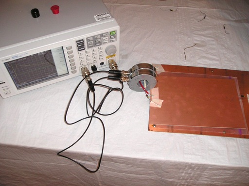
Figure 1. Test Setup For Measuring The Resonance of Two Copper-clad Boards Connected by a Wire
Abstract: When circuit boards
are connected by conductors, a resonant circuit results from the
inductance of the conductors and the capacitance between the circuit
boards. A simple method to damp such board resonances is discussed and
measurements presented in the frequency domain. The method
can be very useful if the designer is restricted to only one connection
point between two boards and applies both to a pair of boards or a
single board mounted over a metal chassis. This Technical Tidbit is an
extension of the February 2010 Technical Tidbit time domain results to the frequency domain.
Discussion: Figure 1 shows the
test setup used to generate the data. The setup is composed of two copper-clad boards connected by a wire about
four inches (~10 cm) long, an Agilent N9320B spectrum analyzer, and two
Fischer F-33-1 current probes.
The two boards are separated about one mm or so by a plastic bag. One
of the current probes was connected to the tracking generator output of
the spectrum analyzer and the other was connected to the input of the
spectrum analyzer and used to monitor the current flowing between the
two copper-clad boards in the wire. The tracking generator was set to
its highest output to maximize the measured signal with respect to
measurement noise.
Also shown in Figure 1 are two 22 Ohm resistors to be used for damping the resonance, one at a time. One of the resistors can be seen passing through the current probes using about 4 inches, 10 cm, of wire for the connection between the resistor and the two boards. The other resistor can be seen at the far right side of Figure 1. Figure 2 shows the details of the copper-clad boards, current probes, and resistors more clearly. The resistor on the right can be placed anywhere between the two boards since the size of the two boards are much smaller than a wavelength at the frequencies investigated.
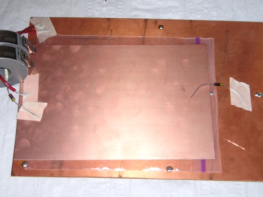
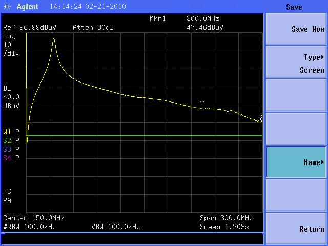
Figure 3 shows the resulting plot on the spectrum analyzer when no resistors were connected between the copper-clad boards. There is a clear peak of tens of dB in the measured current at about 34 MHz denoting the resonance caused by the capacitance between the two boards and the inductance of the wire connecting them that passes though the current probes.
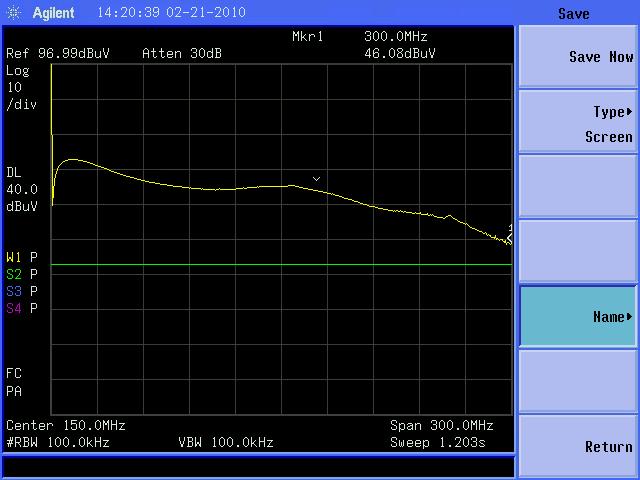
In Figure 4, the result of connecting the 22 Ohm resistor on the right side of Figure 2 between the copper-clad boards is shown. The resonant peak of current is almost completely eliminated!
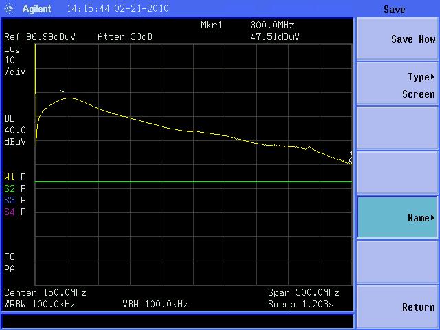
Figure 4. Current Measured Between Two Copper-clad Boards at 1 mm Spacing With 22 Ohm Damping Resistor Used
(Vertical scale = 10 dB/div, Horizontal scale = 30 MHz/div)
The result of separating the boards by about an inch, ~2.5 cm, using a paperback book as the spacer and with no damping resistors connected is shown in Figure 5. The increased board spacing has decreased the capacitance between the boards and thus raised the resonant frequency to about 75 MHz. When the 22 Ohm resistor on the right side of Figure 2 was again added, the result is shown in Figure 6. The 75 MHz resonance is damped to the point of not being visible in Figure 6.
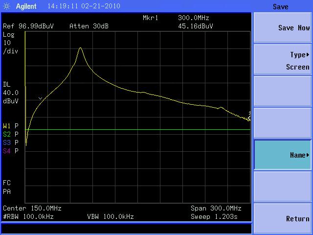
Figure 5. Current Measured Between Two Copper-clad Boards at 2.5 cm Spacing With No Damping Resistors Used
(Vertical scale = 10 dB/div, Horizontal scale = 30 MHz/div)
In Figure 7, the test setup has returned to a board spacing of about 1 mm, but the 22 Ohm damping resistor passes through the current probes. Note that, compared to Figure 4, there is some damping, about 10 dB, but not as much as shown in Figure 4, about 20 dB. This is due to the longer length of the wire needed to connect the resistor through the current probes. The added inductance of the longer wire is reducing the effectiveness of the 22 Ohm resistor, pointing to the need to keep the lead lengths of the resistor as short as possible to minimize inductance.
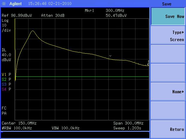
Figure 7. Current Measured Between Two Copper-clad Boards at 1 mm Spacing With a 22 Ohm Damping Resistor Passing Through the Current Probes
(Vertical scale = 10 dB/div, Horizontal scale = 30 MHz/div)
Also shown in Figure 1 are two 22 Ohm resistors to be used for damping the resonance, one at a time. One of the resistors can be seen passing through the current probes using about 4 inches, 10 cm, of wire for the connection between the resistor and the two boards. The other resistor can be seen at the far right side of Figure 1. Figure 2 shows the details of the copper-clad boards, current probes, and resistors more clearly. The resistor on the right can be placed anywhere between the two boards since the size of the two boards are much smaller than a wavelength at the frequencies investigated.
Figure 2. Close-up of Test Setup
Figure 3 shows the resulting plot on the spectrum analyzer when no resistors were connected between the copper-clad boards. There is a clear peak of tens of dB in the measured current at about 34 MHz denoting the resonance caused by the capacitance between the two boards and the inductance of the wire connecting them that passes though the current probes.
Figure 3. Current Measured Between Two Copper-clad Boards at 1 mm Spacing With No Damping Resistors Used
(Vertical scale = 10 dB/div, Horizontal scale = 30 MHz/div)
(Vertical scale = 10 dB/div, Horizontal scale = 30 MHz/div)
In Figure 4, the result of connecting the 22 Ohm resistor on the right side of Figure 2 between the copper-clad boards is shown. The resonant peak of current is almost completely eliminated!
Figure 4. Current Measured Between Two Copper-clad Boards at 1 mm Spacing With 22 Ohm Damping Resistor Used
(Vertical scale = 10 dB/div, Horizontal scale = 30 MHz/div)
The result of separating the boards by about an inch, ~2.5 cm, using a paperback book as the spacer and with no damping resistors connected is shown in Figure 5. The increased board spacing has decreased the capacitance between the boards and thus raised the resonant frequency to about 75 MHz. When the 22 Ohm resistor on the right side of Figure 2 was again added, the result is shown in Figure 6. The 75 MHz resonance is damped to the point of not being visible in Figure 6.
Figure 5. Current Measured Between Two Copper-clad Boards at 2.5 cm Spacing With No Damping Resistors Used
(Vertical scale = 10 dB/div, Horizontal scale = 30 MHz/div)
Figure 6. Current Measured Between Two Copper-clad Boards at 2.5 cm Spacing With 22 Ohm Damping Resistor Used
(Vertical scale = 10 dB/div, Horizontal scale = 30 MHz/div)
(Vertical scale = 10 dB/div, Horizontal scale = 30 MHz/div)
In Figure 7, the test setup has returned to a board spacing of about 1 mm, but the 22 Ohm damping resistor passes through the current probes. Note that, compared to Figure 4, there is some damping, about 10 dB, but not as much as shown in Figure 4, about 20 dB. This is due to the longer length of the wire needed to connect the resistor through the current probes. The added inductance of the longer wire is reducing the effectiveness of the 22 Ohm resistor, pointing to the need to keep the lead lengths of the resistor as short as possible to minimize inductance.
Figure 7. Current Measured Between Two Copper-clad Boards at 1 mm Spacing With a 22 Ohm Damping Resistor Passing Through the Current Probes
(Vertical scale = 10 dB/div, Horizontal scale = 30 MHz/div)
The
value of 22 Ohms used for the resistor caused significant damping of
the resonance between the two copper-clad boards. This value will vary
for different dimensions of the boards and their spacing as well as
with the inductance of the connection between the boards. A value near
optimum can be calculated to be equal to the capacitive reactance of
the two boards at resonance (using the parallel plate capacitor
formula). A good on-line calculator for parallel plate capacitance can
be found here.
The inductive reactance of the connection between the boards could also
be used since at resonance it is equal to the capacitive reactance, but
the inductance of the connection is more difficult to calculate than
the capacitance between the boards.
Summary:
Current probes and signal injection were used to investigate the
resonance between a circuit board and nearby metal (chassis or another
board) connected by a conductor. In particular, the resulting resonance
was shown to be damped
by a resistor of a few tens of Ohms between the circuit board and
the nearby metal. Inductance of the damping resistor connection was
shown to be important and it should be minimized. The damping resistor
can be connected between the two boards at the same point as a single
point connection of the two boards if a single point of connection must
be maintained.
Additional articles on this website related to this topic are:
- Current Probes, More Useful
Than You Think (~170K)
(1998 IEEE EMC Symposium paper) - January 2006, A Small Change Can Have a Large Effect
- October 2007, Using Noise Injection for Troubleshooting Circuits
- November 2007, Measuring Structural Resonances in the Time Domain - Part 1
- December 2007, Using Current Probes to Inject Pulses for Troubleshooting
(Current Probes, More Useful Than You Think - Part 2) - March 2009, Using Current Probes to Inject Pulses for Troubleshooting - Part 2
(Current Probes, More Useful Than You Think - Part 3) - April 2009, Construction of a Series 50 Ohm Termination
- May 2009, Using a Series 50 Ohm Termination With a High Voltage Transient Generator
- January 2010, Using Current Probes to Inject Pulses for Troubleshooting (Board Resonances) - Part 3
(Current Probes, More Useful Than You Think - Part 4) - February 2010, Damping Board Resonances Using Discrete Resistors
- The spectrum analyzer used in this Technical Tidbit is an Agilent N9320B
- Fischer Custom Communications F-33-1 current probe
- Fischer Custom Communications TG-EFT high voltage pulse generator
Need help with a design or additional training on technical subjects? Click on the image below to go to CircuitAdvisor.com, a new engineering resource for training, news, and fun.

If you like the information in this article and others on this website,
much more information is available in my courses. Click here
to see a listing of upcoming courses on design, measurement, and
troubleshooting of chips, circuits, and systems. Click here to see upcoming seminars in Newport Beach, CA.
Click here for a description of my latest seminar titled (now also available online as a WebEx seminar):
EMC
Lab Techniques for Designers
(How to find EMC problems and have some confidence your system will pass EMC testing while it is still in your lab).
(How to find EMC problems and have some confidence your system will pass EMC testing while it is still in your lab).
Home