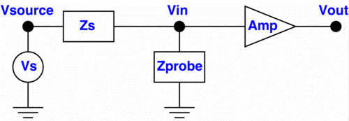
Figure 1. Simplified Probing Circuit
Abstract: As circuits have become faster, active scope probes have become more sophisticated in order to measure today's very high speed signals. At the same time, probe loading of measured signals has become more of an issue. The question of whether to display the signal at the probe tip or to estimate what the signal was without the probe is an important one that designers must take into account. Implications of this choice are discussed.
Discussion: Figure 1 shows a simplified measurement circuit. Vs and Zs compose the Thevenin equivalent circuit at the node to be measured. Vin is the node to be measured with Zprobe being the input impedance of the probe, and Amp being the active circuitry in the probe. There are two Probe design philosophies to be discussed. These are shown in Table 1.
 |
 |
View Signal as Original |
View Signal as Probed |
Table 1. Two Choices in Probe Design
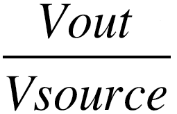
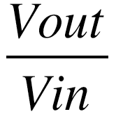
The two approaches to probe design are to either display the voltage at node Vin as accurately as possible at Vout or attempt to reconstruct the Thevenin Vsource at Vout. If the probe's input impedance, Zprobe, is high relative to Zs, the two methods are equivalent. But most active probes today have input impedances that dip to a range of 15 to a few hundred Ohms in the upper octave of their advertised frequency range, especially if one includes effects of short connections from the probe to the circuit. Displaying Vout/Vsource can show a sharp waveform, but may be hiding the fact that probe loading may be affecting circuit operation. A Vout/Vin response makes no assumptions about the circuit or probe and shows the signal as loaded by the probe.
It is compelling to try and reconstruct Vout/Vsource, but to do so requires knowledge of Zs. If Zs is known, there is some value in reconstructing Vout/Vsource. One can "see" the unloaded signal at Vin. If one has to pick an assumption for Zs, the most reasonable assumption would be that Vin is a point on a 50 Ohm transmission line and Zs = 25 Ohms (resistive).
In my experience, when I am in the lab troubleshooting circuits, 50 Ohm transmission lines are only a small fraction of the structures I am probing. Power to ground, ground to ground, ground bounce, even the outputs of most gates do not fit the 25 Ohm resistive source model. If Zs is not 25 Ohms resistive and the probe is designed to display Vout/Vsource for a 25 Ohm resistive source impedance, there will be error in the output. In some common cases, the error can be significant. Care must be taken to match a probe to its intended use.
Additional Material: An in-depth audio-visual format tutorial on this subject, covering background as well as more technical details, is available at: http://emcesd-p.com.
If you like the information in this article and others on this website, much more information is available in my courses. Click here to see a listing of upcoming courses on design, measurement, and troubleshooting of chips, circuits, and systems.
Additional information on this site regarding probing effects includes:
- Balanced Probe Extends High-Frequency Measurements (~3.5MB)
- (1994 IEEE Circuits & Devices Magazine article)
- July 1999: The Shorted Scope Probe Problem
- April 2001, Measurement Error Caused by Probe Input Impedance
- September 2001, Improving FET Probe Immunity to Unwanted Noise Pickup
- November 2001, The Elusive Glitch - Part 2
- August 2002, Probe Input Impedance Revisited - Active Probes
- September 2002, Kirchoff and Faraday Voltage Measurements - Don't Confuse Them
- November 2002, Measuring Noise Voltage Across Seams in Enclosures
- March 2003, Minimizing Errors in Oscilloscope Measurements
- July 2003, Measuring E-Field Coupled IC Chip Noise
- August 2003, Sin(x)/x, The Forgotten Setting - Part One
- September 2003, Sin(x)/x, The Forgotten Setting - Part Two, An EMI Example
- October 2003, Heisenberg and Signal Measurements (A variation on the Uncertainty Principle)
- January 2004, Determining the Effects of Probing on Signals - Tuned Probe Simulators
